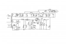
I'm building the attached 6x4 power supply. I will be using it for two preamp projects. One is the Matisse fantasy which I already have built and the other is Frank's 6SN7. Two separate boxes and dual mono. So space is not an issue.
Here's my question. The attached schematic shows three 150uf electrolytic caps. If I wanted to use polypropylene caps like Solen Fast-caps what value would I need to use? If the poly caps are better how much better and would it be best to use them to replace all three of the 150uf electrolytic caps or just the C7 which is connected to the B+1. Or would I be better served to just use some good electrolytic caps like the Panasonic TS with an mkp cap bypass.
I really don't mind spending the extra money for the Solen's or has anyone tried the Jantzen caps but only if the performance is worth it? Your comments and thoughts would be appreciated. BTW I have heard this power supply used with several other preamps and was very impressed but I'm the kind of guy that always wants more. " Don't we all"?
Attachments
Agreed; value is specified by design; a Farad is a Farad.
As for dielectric (and parasitic issues) choice; ALL capacitors have some parasitic inductance and series resistance. It is a matter of bandwidth, and ONLY concerns high frequency. All capacitors (damaged ones notwithstanding) are open-circuits at DC and have an impedance of 1/Cs (1/2/pi/f) until such a high frequency that parasitics become an issue. I have come to understand that this frequency is generally accepted to be the lowest (i.e., most problematic) for [aluminum / conventional] electrolytic caps of a given value compared with other technologies. Lead wires, rolling of foil 'plates' within, etc. contribute to these effects, and ultimately nothing is totally without losses (ohms).
Frequency response graphs of reactance magnitude for various real-world capacitors ALWAYS look about the same, with two main variables: 'resonant' frequency and minimum 'resistance'; there is no perfect cap. It is a damped series resonant circuit. With very low series resistance the trough deepens and sharpens (described by a third variable, the "quality factor"), but on either side of this trough the impedance slopes up-and-away, basically V-shaped as with any series resonant circuit. On the decreasing frequency side, the slope is due to the commodity capacitance (i.e., what you are paying for), and on the increasing frequency side, it is due to the parasitic inductance. At resonance the reactance is purely resistive and at a minimum, which relates to the equivalent series resistance, which is often specified. Generally the minimum is lower and at a higher frequency for "specialized" caps (be assured that the price will not guarantee this). Placing such caps in parallel with your electrolytic cap merely provides a lower impedance shunt path at higher frequencies while doing little if anything to the in-band capacitance. Ideally the V moves to the right (higher frequency) and maybe even a little bit down (lower ohms) for each cap used to bypass. If not it is a waste of time and money; entirely pointless. If you could move the V downward AND to the right, along the capacitive slope, you would be edging toward the perfect capacitor, by diminishing resistance and inductance without affecting capacitance. A key point is that this is impossible at a given level of technology.
Bear in mind the caveat that low ESR is more advantageous than simply moving or sharpening (reducing resistance at) resonance as well... Across the band of interest the entire idea is that the capacitor will pass dynamic current. As frequency increases at a given voltage, so does dynamic current through a capacitance... The ESR is always along for the ride in *series*. The entire V-shaped graph is shifted upwards from the theoretical L-C circuit because of it. It produces the losses, heating, and signal degradation before ever approaching resonance and inductive issues. A bypass cap can only go so far because it is a relatively more open circuit to a higher frequency and cannot help with its parallel resistance until frequency causes its capacitance to be a more friendly path for dynamic current. I say dynamic current as opposed to alternating current since for instance a step-change does not alternate but when it is applied on a capacitor a current flows to charge or discharge it. What this caveat essentially means is that a bypass cap MIGHT just be more of a talking point than an actual help if the frequency band does not actually utilize it. I figure they are cheap enough to just go ahead and include them.
edit: I should mention that paralleling fractional value caps (e.g. using 2 100uF caps in parallel in place of 1 200uF cap) may effectively reduce ESR and parasitic inductance, each by the same factor (in this case by halving it; relative to one of the *100uF* caps). Also may more judiciously utilize PCB layout that way. I say "*may* effectively reduce" since you would shoot yourself in the foot if the 200uF cap was a high-tech, low-esr one and each 100uF cap had at least twice the ESR of the 200uF one. ESR does not strictly depend on commodity capacitance.
A hypothetical case, qualitatively explained: A moderate (say ~100uF) electrolytic cap is specified. With frequency the impedance decreases until it can not any more; it reaches its resonance minimum. A small (say 100nF) ceramic cap is placed in parallel. As frequency continues to increase, the rising inductive slope transitions to a shunt resonance maximum between the two caps and then assumes the decreasing slope of the ceramic cap. Eventually (with rising frequency) the same thing happens. A tiny (say 100pF) mica (etc.) cap will cause the process to repeat, until eventually there is not a sufficiently inductance-free component that can be used to cause the impedance to depart from the rising slope of the final inductance, and it takes over. Probably into GHz at this point, and then who cares. Bend a current-carrying wire slightly and you would see similar inductance effects in a high enough frequency range. There is NO zero impedance at infinite frequency, it would surely upset Einstein.
When I am using electrolytic caps (because they are generally cheap and volume-efficient), I always bypass them. If in a precision signal path involving substantial impedance (audio, feedback, sensing, etc.) where bandwidth is an issue, I use a ceramic or plastic cap (such as 100nF) and a mica cap (such as 100pF) in parallel, which obviously raises the capacitance by 0.1001uF - A pittance alongside a 150uF electrolytic capacitor. Frequency response will not change barring parasitic effects, and bandwidth will be extended considering parasitic effects.
In lower-impedance signal paths, such as passive crossovers, I use spec-value plastic caps until size or cost becomes an issue (with decreasing frequency/increasing farad value); usually using polypropylenes up to about 20uF. From there I use electrolytics. Every one gets paralleled with a tiny 0.1uF cap of whatever type seems in-vogue at that time for low esr, such as mylar.
If the capacitor is not a signal-path component, I just use an 0.1uF cap in parallel (bypass) with any electrolytic. I generally do this for all designs; digital and analog. With digital I don't bother going beyond electrolytics and ceramics. If a large "tank" is needed (say 1000uF and up), I'll usually bypass that with a small (say 10uF) electrolytic and a smaller (say 0.1uF) ceramic in the same way. Small electrolytics are on this transition frequency continuum somewhere between big electrolytics and specialty caps.
Electrolytic caps have their share of problems (relating to chemistry, leakage, reverse polarity), but they store "C" coulombs per applied volt just like any other capacitor.
Last edited:
just a quick experience I have to share -
I built a test platform EF86 connected-as-triode linestage that utilized a 6922 White Cathode Follower.
It started with a series regulator using a 6BM8 tube. The sound was very good with Solen capacitors and chokes in the power supply before the 6BM8. Another choke and Solen followed afterward for the EF86 section.
On a whim, I pulled the regulator and switched over to a choke input supply. I preferred the sound. I then replaced the Solens with Nichicons electrolytics (different values - mind you) and preferred that sound!
Based on some other experiments and projects, I prefer a) unregulated power supplies with chokes and high quality film/electrolytics. b) shunt regulated supplies with film/electrolytics. c) anything that isn't a Solen")
I built a test platform EF86 connected-as-triode linestage that utilized a 6922 White Cathode Follower.
It started with a series regulator using a 6BM8 tube. The sound was very good with Solen capacitors and chokes in the power supply before the 6BM8. Another choke and Solen followed afterward for the EF86 section.
On a whim, I pulled the regulator and switched over to a choke input supply. I preferred the sound. I then replaced the Solens with Nichicons electrolytics (different values - mind you) and preferred that sound!
Based on some other experiments and projects, I prefer a) unregulated power supplies with chokes and high quality film/electrolytics. b) shunt regulated supplies with film/electrolytics. c) anything that isn't a Solen
- Status
- This old topic is closed. If you want to reopen this topic, contact a moderator using the "Report Post" button.