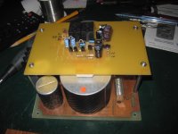
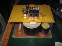
Recapping power supply of a Pioneer SA-7800 (4x8000uf/50V)
Prefer Nichicon KW over KG type 1&2 however the KW only comes in 10000
and 6800uf sizes.
Is it ok to use a 10000uf+6800uf combo on each side. The extra 800uf is within
tolerances. The question is about partnering a big and smaller capacitor together.
Are there any issues (ripple?) that I should be aware of. I would prefer not to use
2x10000uf/side (25% increase!)
Thanks
/second dumb question for the day
Recapping power supply of a Pioneer SA-7800 (4x8000uf/50V)
Prefer Nichicon KW over KG type 1&2 however the KW only comes in 10000
and 6800uf sizes.
Is it ok to use a 10000uf+6800uf combo on each side. The extra 800uf is within
tolerances. The question is about partnering a big and smaller capacitor together.
Are there any issues (ripple?) that I should be aware of. I would prefer not to use
2x10000uf/side (25% increase!)
Thanks
/second dumb question for the day
Why wouldn't you use 4 x10000µF ?
Increasing the capacitance places greater strain on transformer and to a lesser extent rectifier diodes (inrush current). I would expect that the transformer to be over designed to some extent, however the 25% increase reduces this margen, an unnecessary risk imo.
A pair of caps are connected to the positive rail, the other pair to the neg. Each rail is then connected to the L&R channels, so one of the four caps does not uniquely supply any part of the circuit.
A pair of caps are connected to the positive rail, the other pair to the neg. Each rail is then connected to the L&R channels, so one of the four caps does not uniquely supply any part of the circuit.
No.Increasing the capacitance places greater strain on transformer
Only marginally so.and to a lesser extent rectifier diodes (inrush current).
And the new charging pulse from 0V , which happens only once when you turn amp on will last, say, 1.2 seconds instead of one second , hardly a problem.
Inrush current won't be higher because winding resistance limits that.
Which 25% increase?I would expect that the transformer to be over designed to some extent, however the 25% increase reduces this margen, an unnecessary risk imo.
Plus 10000uF is totally in the tolerance range of 8000uF ones and viceversa.
Like others, also suggest you go for 4 x 10000uF caps which to boot may even be physically smaller than originals, worst case same size.
Don't overthink it, you have an excellent amp and if anything, it will work better now
")
JMFahey, yeah, I agree with your sentiment and will probably go with 4x10000uf, however I'm not sure if I agree with everything you say. I'm sure you know that transformers are VA rated, increasing inrush (A)... Also 10000uf +10/20% is outside 8000 +10/20% but you are right not to overthink the problem. Sadly the amp is not mine hence the extra care. It is gorgeous, need to take care of the remaining few.
Thanks again for your comments.
Thanks again for your comments.
JMFahey, yeah, I agree with your sentiment and will probably go with 4x10000uf, however I'm not sure if I agree with everything you say. I'm sure you know that transformers are VA rated, increasing inrush (A)... Also 10000uf +10/20% is outside 8000 +10/20% but you are right not to overthink the problem. Sadly the amp is not mine hence the extra care. It is gorgeous, need to take care of the remaining few.
Thanks again for your comments.
Great that you're finding out about something as straight forward as the power supply capacitors - attention to detail is important!
I would say 4x10,000uF, I wouldn't worry about inrush current at all. Capacitors will almost certainly have much lower series resistance than the transformer.
More important than the capacitance is the current rating of the capacitors. Those 8000uF may be rated for 5 or 6 A ripple (at the given standard operating conditions), but your replacements may only be rated at 2 A, which will place massive strain on the capacitors and premature failure. Make sure you match the ripple current specifications.
Increasing the capacitance places greater strain on transformer and to a lesser extent rectifier diodes (inrush current).
This is negligible and greatly exaggerated in vintage audio circles.
This is negligible and greatly exaggerated in vintage audio circles.
Hi,
Not really. The capacitance you can load a rectifier tube
with is rather limited. That is where the idea started.
rgds, sreten.
Larger capacitors, all told, DO increase the strain on diodes and transformer - and PLEASE do I REALLY need to post sim or measurement results to show this?
The main limit in the height of a current pulse that charges the caps on every half cycle is a combination of stray inductance and series resistance of the transformer windings - take a toriodal transformer as an example, where the resistive portion is negligible, and in fact this is what is usually strive for for good regulation. Then the fact remains, larger cap = higher pulse. All of this is fine as long as:
a) the peak current is below the ampere-winding limit of the core (i.e. below core saturation)
b) the peak current does not significantly aggravate the reverse recovery of the rectifiers
c) The transformer is not already pushed harder by the mains voltage being higher than the nominal for the transformer primary (i.e. 230V mains on a 220V transformer, in a high mains voltage situation).
In case of restoring a vintage amp, it's actually not too difficult to predict how far you can safely push the capacitances - just look at the tolerances on the original caps. In general, older cap technologies were not as good at getting and maintaining the spec so the + tolerance was quite high - often +30%, sometimes even +50%. This is the amount you can completely safely increase the capacitance. For all other cases, do not just put the caps in and, oh well, look, it works. The proper test would be to push the amp to full spec, THEN see how the transformer and rectifiers behave. Granted, amps only do this in peaks but doing this for a period of time is the real test - and what the whole thing was designed to do.
Sorry, no. At turn on for the first 3 or 4 cycles, you might push between 1 and 5 more amps per cycle. After that, charging current will remain exactly the same, whether you push the amp hard or not. Charging currents are very high - peaking at 50 - 100 A on start up. 1 - 5 more amps won't make any difference. Series resistance of lower than 0.2 ohm will show larger differences, but this is unrealistically low resistance for a secondary coil.
Peak current ratings of rectifiers are usually >100 A, and if you're close enough to this with 16000 uF per rail that you can't go to 20000 uF, then your design is poor. I seriously doubt the amplifier will be operating anywhere near -10% of the peak current rating of a rectifier!
Saturation of your core will not be a problem if the peak current is 100 A for a few cycles. It's never going to heat up in 0.1 s.
And resistance of a transformer is most certainly not negligible. 35 V in 0.001 ohms is 35,000 A, and 35 V in 0.4 ohms is 87.5 A.
The important current to consider in your transformer is the average current. Same with your diodes. For the capacitors, they need to handle the ripple current required for the amplifier's current needs. Average current will not be affected by different capacitance.
What calculation do you use to select your power supply capacitors?
Last edited:
The important current to consider in your transformer is the average current.
Most certainly NO. Transformers are not wound for average, but for PEAK current. You are aware that transformers for resistive loads are wound for a higher Bmax than ones used with rectifiers, and in fact the typical value for toroidal transformers for resistive loads like halogen lamps is around 2T (and note, the lamp has a VERY low resistance at startup so i am not talking abut the few startup cycles!), while a typical transformer wound for a rectifier application is would for about 1.7T. Where do you think this value came from? A rectifier with a capacitor filter is NOT a resistive load, so neither is peak current directly related with the load, it does not even occur in phase or indeed for the whole duty cycle (hence has to charge the capacitor enough to cover the whole duty cycle). It might surprise you it comes from a TABLE pre-calculated for a certain filter capacitance per ampere of load current - calculated from the maximum PEAK current expected from that setup. And it's obviously not SQRT(2)*RMS, but rather higher.
Homework: put a small winding on a loaded transformer driving a load through a rectifier and filter - then look at the secondary voltage with respect to load current and filter capacitance. At some point the tops will become flat. What do you think happened there? True, as long as it does not happen, you are mostly fine.
Why mostly? Because the shape of the peak current does have some added effect due to iron losses. A shape with less high harmonics will generate lower losses (And keep in mind they go up with harmonic frequency squared).
Ever designed a switching power supply?Same with your diodes.
Have a look at what happens due to reverse recovery and how it relates to PEAK current. Yes, the average current is to the first approximation indeed the same, but that's not what causes these problems. Note: absolute maximum current for the peak is dependent on reverse recovery, because during reverse recovery the diodes are sucking out the charge out of the capacitor, the longer the higher the peak was during the proper direction. So, more peak current, less remaining voltage. Of course, it comes down to properly choosing diodes, and the question, are they indeed?
Granted. But what current heats up the capacitor's internals? Average current of the power supply?For the capacitors, they need to handle the ripple current required for the amplifier's current needs. Average current will not be affected by different capacitance.
Simulate it. Starting form a standard transformer calculation for some 1.7T or, depending on experience, knowing in advance some of the parameters (such as very large filter capacitors) lower, then depending on peak vs average current you go back and adjust the transformer specs (in case you are doing a custom transformer), or adjust the filters if you have an off-the-shelf transformer. Warning: most diode models do not simulate reverse recovery. So, some use of the graphs in the diode datasheet is to be expected.What calculation do you use to select your power supply capacitors?
...And i just lost an entire long post.
The point of which was, how far you can push the filter caps depends to the largest degree on the dimensioning for the transformer, then to a smaller degree on the rectifiers.
It IS indeed possible to dimension the transformer so that the internal resistance and stray inductance sufficiently limit the peak current in the secondary (and therefore the rectifiers) that it is irrelevant what size capacitor is used as a filter. However, this is rarely the case as such a transformer is by todays standards woefully over-dimensioned, hence unoptimized and needlessly large and expensive. Which in other words means that you are more likely to be able to increase the capacitance of the filters on old TOTL amplifiers because money was less of an object for their construction. But, it is not really a given. The discussion I posted above is not meant as an 'is always true' but a consideration of borderline conditions one needs to look into and take into account.
Of course, the fact remains that more capacitance means more or longer 'startup' and the very probable need to deal with the increased inrush current.
Ilimzn, besides your ramblings, an increase from 16000uF to 20000uF isn't going to be a problem. Calculate it or simulate it, either way you'll see little difference in start up and no difference in steady state.
And when you design a power supply, don't simulate it, calculate it. A fairly average transformer for a normal amplifier (being stereo, and more or less 200 - 300 VA) will have in the region of 200 m of copper wire, which has significant resistance. Capacitors have series resistance. And these resistances will dominate the non-real part of the impedance at mains frequency. When you calculate a power supply, calculate ripple voltage, and in most cases it's not relevant to calculate safety margin, unless you're using really large capacitances. I'm running almost 30000uF per rail on my small amplifier using a 225VA, 18Vac transformer, and there is no problem.
And when you design a power supply, don't simulate it, calculate it. A fairly average transformer for a normal amplifier (being stereo, and more or less 200 - 300 VA) will have in the region of 200 m of copper wire, which has significant resistance. Capacitors have series resistance. And these resistances will dominate the non-real part of the impedance at mains frequency. When you calculate a power supply, calculate ripple voltage, and in most cases it's not relevant to calculate safety margin, unless you're using really large capacitances. I'm running almost 30000uF per rail on my small amplifier using a 225VA, 18Vac transformer, and there is no problem.
As I said - 15000uF +30% (typical spec for the time) ~ 20000uF which will typically today be +0 - 10%, so as I said, one can use that as a 100% safe calculation. There are some possible benefits of using two different caps but that's a whole other story that does not have to do with the basic functionality of the power supply.
And re power supply, I do indeed calculate it, and moreover, measure the components, THEN simulate with realistic values. Slapping a source + bridge + capacitor + resistor into a simulator does not simulate a real power supply.
Also, there are 225VA and 225VA transformers, if you know what I mean.
And re power supply, I do indeed calculate it, and moreover, measure the components, THEN simulate with realistic values. Slapping a source + bridge + capacitor + resistor into a simulator does not simulate a real power supply.
Also, there are 225VA and 225VA transformers, if you know what I mean.
Never seen an amplifier fail in any way due to increased filter caps... Most rectifiers used in them have a surge rating of at least 10x of their nominal value (usually 50-100A), the short overload on the transformer should present no problem either. One possible problem is the fuse(s), but even those should survive unless they are the fast blow types (which are seldomly used in amp power supplies anyway).
Yes, in this case, the diode current isn't a big deal, but it's not just a thing that happens at turn-on, it happens at each half cycle of the power line. The easiest way to think about it is that if the amp is consuming say 500mA on average, this current gets sent to the caps only when the diodes are conducting, which is when the caps have bled down to below the transformer/diode voltage. So, the caps are charged for only a portion of the entire half cycle of the power line.
In this example, if 500mA average is needed and the diodes only conduct 10% of the time, the peak current will be roughly 5A. With larger caps, the voltage droop on each cycle that happens as the caps supply the load will be less, so the diodes will not be conducting for as great of a percentage of time. This means that the peak currents will be higher. Roughly, double the capacitance and the peak diode currents should go up by about 2x. But again, this is not a turn-on issue, it happens at every half cycle of the power line.
Practically, diodes can withstand huge peak currents, limited mostly by the limits of any bond-out wire used, which isn't even done with high current power diodes - the die is just soldered top and bottom to big slabs of metal that form the leads. So, changing the cap size doesn't increase the average dissipation, just the peak diode current - as was stated earlier, it's not such a big deal in this case.
Never seen an amplifier fail in any way due to increased filter caps...
Maybe you haven't seen one where somebody put half a farad where 10,000 uF used to be. That will blow rectifiers unless you up-size them. By a lot. Possibly blow breakers too, unless a soft-start circuit is added. Upgrading to the next size up should never be a problem, but there are those out there that go from the ridiculous to the sublime when it comes to filter caps. That is what is never a good idea without thinking things through and accounting for increased stresses.
- Status
- This old topic is closed. If you want to reopen this topic, contact a moderator using the "Report Post" button.
- Home
- Amplifiers
- Solid State
- Capacitance 2x8000 = 10000+6800