I could do with some help with fixing my PM-94. ")
The Marantz has been recapped and all solder joints expected. It appears to function well however there are the following problems:
1. The left heat sink gets really hot while the right one is much cooler. The first step of biasing the left channel to 36 mV is possible, however the second step of biasing to 180mV not (initially it appears to work when turning the trimmer, but then it jumps back and forth in value).
2. Biasing the right channel works in both steps, however the heat sink gets warm but not hot. My feeling is that it's working in class a/b (perhaps this could be related to the quarter A settings?).
3. Have some difficulties to get the DC offset set to 10mV (and it seems to fluctuate).
1. What would be the most likely cause for this erratic behaviour of voltage jumping to different values?
2. Could the quarter A settings cause the right channel to work cooler (in class a/b) while bias settings in both steps are set to resp. 36mV and 180mV?
3. The DC offset changes with the bias and is difficult to keep at 10mV in the right channel. Any idea what might cause this? (am able to set it to around 8 or 14, but then it changes)
All tests were done at least after one hour.
Hopefully someone can point me in the right direction.
Attachments
The DC offset should be adjusted to zero. The -/+ 10mv is a tolerance and may be an optimistic one in practice. If the offset is below -/+100mv then it will cause no issues however the correct point to aim for is zero when the amp is warmed.
If the amp has had work done to it (particular if transistors have been replaced) then its possible the bias issue may in fact be oscillation rather than a DC problem. That is more likely if you can set both to the correct 36mv point and yet one heatsink is then much hotter than the other. You need to use a scope to look if this is the case.
You also need a scope to check that the adjustable bias circuit is being turned on/off correctly.
If the trim pots adjust smoothly then I doubt there is a problem. 25k should work to prove/disprove there is an issue but the value of 20k looks somewhat bizarrely as if it plays a part in the overall gain structure. However the change from 20 to 25k would be minimalI've just bought some trimpots and was wondering if I could use a 25K ohm instead of a 20K ohm to adjust the output offset voltage. Is there any risk in trying these or should I order the 20K ohms?
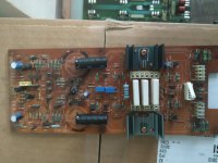
I decided to finally replace the trim pots with exactly the same values as before. Have resoldered all the transistors and other parts that were exposed to the heat. Was wondering Should I replace all transistors as a precaution, since the ones on the left were exposed to great heat and measured different than the ones on the right in circuit?
Or should I just fire it up and see how the bias behaves?
Or should I just fire it up and see how the bias behaves?
Attachments
I would not replace transistors at this point. Get the amp working correctly first. Remember what feels hot to you is not necessarily hot for a transistor. If they sizzle a drop of water then that is starting to get to hot. If you can bear to touch it for even a couple of seconds then it is not hot enough to cause failure.
Yes it is possible but that would be extreme heat, the sort of heat where a transistor actually starts to melt the solder for example.
Remember that to accurately check the transistors needs them removing and very detailed and involved testing to take place. You won't pick up meaningful differences just doing static checks in circuit.
Remember that to accurately check the transistors needs them removing and very detailed and involved testing to take place. You won't pick up meaningful differences just doing static checks in circuit.
I managed to locate the PN00 board, but that particular page is of a very low resolution... I am trying to locate that Q107... but I can't... Did you follow the "4. ADJUSTMENT PROCEDURE" ?
Also, the capacitors' re-capping can sometimes result in oscillations. What may seem like a like-for-like replacement (same capacitance and nominal voltage)... might not be a like-for-like replacement due to different ESRs.
May I suggest that you take an amp to a qualified technician/engineer? ..... especially if you like the amp... it seems to me that, initially, you attempted to fix the same amp back in 2020? (I might be wrong, though):
https://www.diyaudio.com/community/threads/marantz-pm94-service-manual.344095/
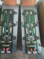
I did a full recap and there's sound. As the left channel was significantly hotter than the right, I decided to check bias etc. For the right channel it's stable, however not for the left. When I checked the transistors in the left channel, the thermal paste was rock hard and very difficult to remove compared to the right. Have now resoldered all parts and replaced paste and mica insulation with Keratherm 86/82 pads.
I have really bad experiences with accredited Marantz service companies, such as Audio service in Elst. Also, not many technicians in the Netherlands dare to undertake such an adventure, hence I try to do it myself with help of experts like you on this forum. I might actually learn something along the line 😸.
I have really bad experiences with accredited Marantz service companies, such as Audio service in Elst. Also, not many technicians in the Netherlands dare to undertake such an adventure, hence I try to do it myself with help of experts like you on this forum. I might actually learn something along the line 😸.
I've replaced all the trimpots, resoldered the amp boards, and replaced the heatsink thermal paste with Kerafol. Bias is stable and measures as in the service manual resp. 36mv and 180mv. The heatsinks are about 85 degrees Celsius, which is incredibly hot (actually feels hotter than before with old tried out thermal paste). Should I be worried, or is it still acceptable?
Maybe there will be less heat once I've adjusted the quarter A settings, but I'm not sure it will be the case.
Maybe there will be less heat once I've adjusted the quarter A settings, but I'm not sure it will be the case.
You have to look at the basics and if they are correct then the heat generation is going to be normal.
You MUST check that the amp is stable using a scope because anything going on there does not always show on simple DC tests with a meter. Assuming that is OK...
I haven't studied the amp in detail but I'm surprised to see what look like linear voltage regulators supplying the output stage. At face value these drop a massive amount of voltage across the series pass transistor which means lots and lots of heat. As shown and looking at the positive rail only for one channel we have 63 volts in and 36 volts out which means 27 volts across the regulator.
Bias currents (at face value). You are setting the current by adjusting the voltage across 0.44 ohms.
Three settings, 15mv, 270mv and 750mv for AB, low A and high A. They give a current of 34 milliamps, 0.61 amps and 1.7 amps.
Assuming 36 volt rails (you need to check these) and looking at the amp as a whole then we have 5 watts dissipation, 88 watts dissipation and 244 watts dissipation. That is just for the amp, not the regulators.
The AB setting should run very cool/cold. Either of the others will generate lots of heat.
You need to look how the regulators work. Are they bypassed on some settings?
So your first check is that the bias is correct at on AB setting and you need to determine what the rails actually are.
Hi Mooly, Thanks for your feedback. I do have a scope, however I'm wondering where the test points are to measure if the amp is stable. Where on the schematic should I measure? TP1-TP3 are for bias and quarter A, are there any other indicated test points?
I will test the rail voltage again just to make sure, however the last time it was approx. 36V and 63V.
On another forum I read a post from ' Rick the Amp Man', in which he mentions that the PM94 has optical feedback biasing circuits and about 20 adjustments that can be made to its various subsystems. I measuring the AB bias when you set the bias with short between TP1 and TP3 (36mv)? And without short between the pins class A (180mv)? If so, I should be able to measure the temperature of the heatsinks in AB mode. This is what they call AVSS (or Automatic Voltage Shift Supply - two voltage rails), right?
Thanks bosedtobosed. Do you mean transistors on the PN00 - comparator/protector/supply circuit board? Or PN00 in combination with QL07/QL08? Or something else?the transistors on the o\p board\hsink supply a higher voltage when needed
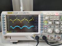
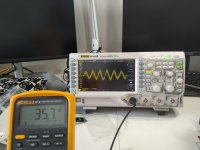
You look across the speaker output with the scope. With no signal you should just see a flat trace with nothing present. Oscillation that would cause issues would be in the several volts peak to peak region and at many 100's of kHz and higher... up into the low to mid Mhz region. So you need a scope that has that kind of bandwidth.
If the rails are plus 36 and minus 36 volts (check both are correct on both channels) and the DC voltage across the bias test points is 15 millivolts (value in my manual) then that is 34 milliamps. The dissipation is 1.22 watts per output transistor and those transistors should be very cool.
If the rails are plus 36 and minus 36 volts (check both are correct on both channels) and the DC voltage across the bias test points is 15 millivolts (value in my manual) then that is 34 milliamps. The dissipation is 1.22 watts per output transistor and those transistors should be very cool.
This is with the scope across the speaker terminals. Somehow I don't here the click of the relay when I switch on the amp anymore. Also, left side is not giving reliable bias readings and heatsink now stays cold (last night bias setting was ok and heatsink was the same temperature as the right).
I will follow your advice and measure all voltages before making any adjustments.
I will follow your advice and measure all voltages before making any adjustments.
Attachments
- Home
- Amplifiers
- Solid State
- Bias problem Marantz PM-94