Hi there, I'm working up a new crossover for what is in essence a FAST system. I generally prefer valve amps and wide range drivers but I've found the bass is lacking in clarity and impact in my current setup (alpair 12P wide range and Eminence Alpha 15 in an H frame).
I experimented with a DJ type active crossover (Citronic ax-4) and used a Topping TP 60 for the bass, worked well down low but wrecked everything else.
I built my own passive Line Level Crossover (RC type) but was not impressed, I drove it from my Rega DAC. It might work better with my more grunty 6n6p preamp but will try that another day.
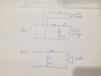
What I am considering doing is running the preamp full range into two power amps, the valve one (6c33c) driving the wide range and supertweeter, the Topping driving the woofers. Building a crossover for each and dumping the surplus power into suitable resistors.
I've attached a diagram to outline the plan, I'd use my current crossover calculations and match the "missing" components with high power resistors.
This is all in an open baffle system I can provide more details if needed but wondered if this had been tried before.
Apart for the wasted electricity do you think this would work, any suggestions?
I experimented with a DJ type active crossover (Citronic ax-4) and used a Topping TP 60 for the bass, worked well down low but wrecked everything else.
I built my own passive Line Level Crossover (RC type) but was not impressed, I drove it from my Rega DAC. It might work better with my more grunty 6n6p preamp but will try that another day.
What I am considering doing is running the preamp full range into two power amps, the valve one (6c33c) driving the wide range and supertweeter, the Topping driving the woofers. Building a crossover for each and dumping the surplus power into suitable resistors.
I've attached a diagram to outline the plan, I'd use my current crossover calculations and match the "missing" components with high power resistors.
This is all in an open baffle system I can provide more details if needed but wondered if this had been tried before.
Apart for the wasted electricity do you think this would work, any suggestions?
Attachments
Last edited:
What I am considering doing is running the preamp full range into two power amps, the valve one (6c33c) driving the wide range and supertweeter, the Topping driving the woofers. Building a crossover for each and dumping the surplus power into suitable resistors.
Yes, this is commonly called "passive bi-amping", and it works.
No need to duplicate the full crossover for both amps and "dump the surplus power into resistors", though. You can just connect the Topping amp to the low-pass section, and the valve amp to the mid-high section.
Marco is right.
The one possible thing I might add is a very high value resistor on tweeter inputs. Around 100 ohms across each input. This will prevent the maximum impedance from going to infinity due to tweeter coil impedance.
Under some circumstances this will prevent ultrasonic oscillations.
It may be worthless, and best with 6-8 Ohm tweets..")
Best,
Erik
The one possible thing I might add is a very high value resistor on tweeter inputs. Around 100 ohms across each input. This will prevent the maximum impedance from going to infinity due to tweeter coil impedance.
Under some circumstances this will prevent ultrasonic oscillations.
It may be worthless, and best with 6-8 Ohm tweets..
Best,
Erik
Thanks guys
Marco- Yes this is basically my previous crossover cut in half. The 8 ohm resistors in the diagram serve this "dumping" purpose and prevent a short circuit at the diverted frequencies.
Eriksquires- Will look into that. I use "air motion transformers" which have a flat impedance response so may not be needed.
Jay- Indeed this is one of the reasons I want to bi-amp.
Steve, have you checked your impedance?
I can't even do a simulation without the part values, but if you don't have another tool grab the free XSim and simulate your crossover components. Even if you can't measure the actual driver impedances, you can get a good feel for what that resistor was doing.
You may need to consider moving the coil to ground after the cap to maintain a better minimum impedance if you remove that resistor.
Best,
Erik
Best,
Erik
Thanks Erik
I checked in X SIm and the impedances are fine, Thee coil does go to ground after the cap in the real crossover. I see the importance of having the first pole of the crossover in line and on the amplifier side so the second pole sees a filtered signal and a resistor isn't needed.
I checked in X SIm and the impedances are fine, Thee coil does go to ground after the cap in the real crossover. I see the importance of having the first pole of the crossover in line and on the amplifier side so the second pole sees a filtered signal and a resistor isn't needed.
Thanks Erik
I checked in X SIm and the impedances are fine, Thee coil does go to ground after the cap in the real crossover. I see the importance of having the first pole of the crossover in line and on the amplifier side so the second pole sees a filtered signal and a resistor isn't needed.
Oh, good. That makes more sense then!
Erik
- Status
- This old topic is closed. If you want to reopen this topic, contact a moderator using the "Report Post" button.
- Home
- Loudspeakers
- Multi-Way
- Bi amp with double passive crossover?