i have some cisco 6000 power supplies i am trying to convert into a dual-rail power supplies (chaining them in parallel, already made sure the neg is not connected to chassis ground).. it outputs various levels of potentials, 3.3v 5v, 12v and 42v.. and i got them for practically free and they're 1300w so should be plenty for all sorts of projects
problem is they output a raw 42v and i wanted to create a 1.25 (or 0) to 30v variable output power supply using something like a lm317 or lt3080 or something along these lines.. Well, none of these regulators would really like 42v being fed into them so i need to lower them to around 36v somehow. I was going to initially resort to a few series diodes (i have a few 12a diodes with a Vf max of 1.5v which i thought would be good enough if i used like 4-5 of them on each side), but after looking at the datasheet of the diode closer, i think the Vf varies a bit that at low loads the Vf would not lower the voltage enough to still not exceed the Voltage Regs' max volt input levels..
So question is basically, how do i get 36V from 42V? The 42V outputs about 27amp and i dont need that much @ 36v but say 6amps would be plenty (i can then chain a few lm7815 and lm7905 to get a few fixed levels as well.
You could use the LM317HV which has the input/output differential voltage raised to 60V allowing you to regulate from 1.2V to 57V.
http://www.ti.com/lit/ds/symlink/lm317hv.pdf
http://www.digikey.com/scripts/DkSearch/dksus.dll?keywordSearch&keywords=LM317HV
http://www.ti.com/lit/ds/symlink/lm317hv.pdf
http://www.digikey.com/scripts/DkSearch/dksus.dll?keywordSearch&keywords=LM317HV
Last edited:
i actually considered the HV version but it looks not that widely available (newark has them) and also if the neg version would be the lm337hv, that's pretty much impossible to find :-\
Hmm, zener darlington and a resistor.. interesting! Would that zener have to be rated at 6amps tho (or the related 42 x 6 watts maybe)? Might get expensive quickly that way tho no? Hmm, circuit.. i might be able to figure it out but if you have a quick overview i wouldn't be opposed to a hint")
Hmm, zener darlington and a resistor.. interesting! Would that zener have to be rated at 6amps tho (or the related 42 x 6 watts maybe)? Might get expensive quickly that way tho no? Hmm, circuit.. i might be able to figure it out but if you have a quick overview i wouldn't be opposed to a hint
Alright did some more research around DUG's proposed arrangement, sorry for the silly question about the zener needing to be high power rating, since seems most of the current would going through the series pass darlington, and the resistor would be used to current limit what went through the zener.. Still one thing that's confusing me though is how did you come up with 4.5v zener, if you're doing 42-4.5 then that makes sense, resulting in 37.5 being something i think the lm317 or lm350 for example could handle, but i'm unclear about that arrangement since the reading i've done to get a better understanding usually has the zener @ the desired output level, e.g. 36v zener in this case.. wouldn't mind using a 4.5v zd instead, just always looking to learn more about how this would work.. thanks for the pointers thus far though!
Assuming you're going to use a pass transistor since LM317's max current is only 1.5A -
Use some resistor divider to make a 36V supply for the LM317. If you can do zener regulated, even better. But not much current will be drawn from this supply. (You'll need to calculate the optimal resistor values.) Output of the LM317 will be regulated anyway.
Output of LM317 feeds the base of the NPN pass transistor (but this concept probably works for configuration with PNP transistor too). The pass transistor will eat 42V on the collector and Vout on the emitter, but now you can easily find a part that can handle that. LM317 will eat max 36V on the Vin pin. Find a transistor with sufficient current gain and select the right resistor values, and variation of Vin (at LM317) due to load current will be negligible.
RJM1, i forgot to mention, i want to do this at both sides, e.g. on the +V and on the -V (which would be a second supply hooked up in parallel to the first). Hence my need for the LM337HV if i went with an HV part on the +V side..
wwenze, interesting.. i hadn't considered that but it is starting to make sense. I was playing with (after just discovering) falstad's analog circuit simulator last night (man that thing is awesome), and the zener approach i couldn't get to be stable w/ varying load currents, so i'll give this approach a try to see if i can get it working right (except his simulator doesn't have discrete IC's like the LM317 so i'll probably just mock up the basic representation of it)
wwenze, interesting.. i hadn't considered that but it is starting to make sense. I was playing with (after just discovering) falstad's analog circuit simulator last night (man that thing is awesome), and the zener approach i couldn't get to be stable w/ varying load currents, so i'll give this approach a try to see if i can get it working right (except his simulator doesn't have discrete IC's like the LM317 so i'll probably just mock up the basic representation of it)
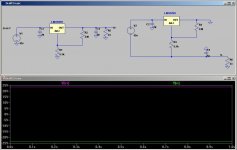
So with DUG's hints.. i came up with this.. the 499 ohm resistor didn't give me that great results so i replaced it with a trimpot for fine adjustments..
it hopefully can help someone else who is looking to do something similar and folks can learn as much as i have from this design Thanks again DUG!
it hopefully can help someone else who is looking to do something similar and folks can learn as much as i have from this design
Thanks again DUG!Dropping voltage
Hi,
If you use a linear regulator to drop that voltage, you'll dissipate a great deal of heat in the regulator. See if you can get the service manual for the CAT 6K router power supplies, or just trace out the last few components near the 12 volt or 42 volt outputs. Somewhere, there's a resistor divider from one of the outputs back to a TL431. It could be a TO-92 or SO-8 package. There may even be a small potentiometer to tweak the output voltage. The divider will be set to send 2.5 volts (or possibly 1.25 volts) to the control pin of the TL431. you can adjust the bottom resistor of the divider to drop the voltage down.
The math is simpler to adjust the top resistor, but the power supply will probably blow up, so you need to adjust the bottom resistor of the divider because that doesn't affect eh stability of the supply.
Where did you pick up the supplies? I need something like that!
Cheers,
Marshall
Yes a linear reg def isn't efficient, but i plan on only dropping to 36v before using something like an lm317 for better load regulation, and then using that, get to say 24v (guess i should mention i ultimately am also going to use an lm7815/lm7915 to get +/-15v (or maybe using a pair of ALWSR's) but the big picture is i plan on making a lab power supply that outputs a variety of fixed levels, 42v (of crz, the main output of these PS's), 36v, 24v, 15v, 12v (also provided by the supply), 9v, 5v (also from the supply) and 3.3v (also via the supply). Same thing on the negative side from a 2nd supply (so i have -42v from the 2nd supplies ground (and the +42v of the 2nd will be tied to the ground of the first, e.g. parallel, as well as all the other voltage levels needed -36, -24v, -15v, etc..).. the result is a various level dual-rail supply thing.. best part is each 1300w version PS can supply ~27amps @ 42v that's a decent amount of audio!
The supplies i got as surplus from work (i work for a financial company and i'm an comp/hw engineer there and regularly work in the server/network lab there), they were getting rid of them (actually they initially had 6000watt supplies but those it turns out they needed still, DOH they're not light too!! i got them home then needed to lug them back, but i eventually then got some 1300watt i hopefully won't have to give back, they are still more than enough power output for hopefully ALL my audio and electronic projects).
I looked around online, they can be had for like 30-50 bucks a piece (that sometimes includes shipping).. with two them one has pretty much a great amount of flexibility (outputting 42/12/5/3.3v) and power headroom.. i also reached out to a contact i have at cisco for the secret elusive pinout of the 6500 series switch power connector so i have a good idea what you can get on what pin.. i didn't think to ask for the service manual as i would really rather not open these guys up (and cisco gives 3rd parties guidelines and other people actually build the supplies so they aren't always manufactered by cisco for there to be an official service manual anyway).
eventually i am looking to maybe create an open source hardware project that anyone can take some cisco 6500 series power supplies and hook them up to this contraption i'm designing, providing you a turnkey solution for various (and eventually variable) voltage lab power supply.
Of course may not be too surprising that i don't have much of an electrical engineer background (other than hobbyist, i did comp sci in school), so i'm picking things up as i go.. if anyone has any other input on the circuit i came up with, i'm all ears.. i actually am curious whether i sized the bypass caps properly on the input/output (i was kind of just pulling numbers out of the air without any scientific approach :-\ so could use some input there or other pointers
that's a decent amount of audio! The supplies i got as surplus from work (i work for a financial company and i'm an comp/hw engineer there and regularly work in the server/network lab there), they were getting rid of them (actually they initially had 6000watt supplies but those it turns out they needed still, DOH they're not light too!! i got them home then needed to lug them back, but i eventually then got some 1300watt i hopefully won't have to give back, they are still more than enough power output for hopefully ALL my audio and electronic projects).
I looked around online, they can be had for like 30-50 bucks a piece (that sometimes includes shipping).. with two them one has pretty much a great amount of flexibility (outputting 42/12/5/3.3v) and power headroom.. i also reached out to a contact i have at cisco for the secret elusive pinout of the 6500 series switch power connector so i have a good idea what you can get on what pin.. i didn't think to ask for the service manual as i would really rather not open these guys up (and cisco gives 3rd parties guidelines and other people actually build the supplies so they aren't always manufactered by cisco for there to be an official service manual anyway).
eventually i am looking to maybe create an open source hardware project that anyone can take some cisco 6500 series power supplies and hook them up to this contraption i'm designing, providing you a turnkey solution for various (and eventually variable) voltage lab power supply.
Of course may not be too surprising that i don't have much of an electrical engineer background (other than hobbyist, i did comp sci in school), so i'm picking things up as i go.. if anyone has any other input on the circuit i came up with, i'm all ears.. i actually am curious whether i sized the bypass caps properly on the input/output (i was kind of just pulling numbers out of the air without any scientific approach :-\ so could use some input there or other pointers
RJM1, sorry didn't pay close enough attention to your post, that looks like it would work, but i am looking to do approx 6amp so i would need a series pass device to be able to handle that amount of current (and your post only had the HV lm317 doing all the heavy lifting).. guess what you posted could be adapted, but i'm rather proud of what i came up with as well
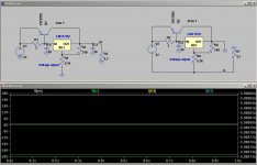
Those two schematics (the pos/neg halves of your latest post) look eerily similar to each other.. why did they produce an LM 337 if you could just use an LM317 in almost the exact same way?
Can you help me understand the difference? Specifically my concern is, with the neg version, isn't it stepping down the common Ground (0v) of the neg half, lower toward the negative extreme? E.g. if you have a 0v @ gnd and -42v at the -Ve side, isn't it stepping down the 0v lower toward the -42v (instead of making the -42v go toward the 0, to -36v? I'm asking because this makes me think the gnd reference will be shifting between both supplies, and with my overall project, the Gnd on the +42v supply is going to be hooked up to the +42v of the second ground (to have that common point be the virtual ground).
I'm basically worried the neg version will make the Gnd really be, with an absolute reference, (as if it was an isolated 2nd supply), 0-42v becoming 0-36v (instead of what i think i need being 0-42v becoming "6-42v").
Sorry if i'm doing a crappy job explaining where i'm concerned, hopefully you get what i'm trying to ask
- Status
- This old topic is closed. If you want to reopen this topic, contact a moderator using the "Report Post" button.
- Home
- Amplifiers
- Power Supplies
- basic power supply questions