I have a vintage ADS RS12 12" Dual voice coil. Got it from the car. I'm going to use it in home as a PASSIVE subwoofer, so the enclosure has been considered. I found its instruction manual on the internet. Here they are. (click on the pictures to enlarge)


I decided to build the enclosure in BAND-PASS type as recommended by the manual since it required no low-pass filter, interpreted by the response curve in the manual as you can see, so I could save the money from buying large inductors.
The problem is as being said from the manual that the recommended port length on the vented chamber is about 17.7 inches.
I went to the online calculator >> Shavano Online - Sub Woofer; 4th Order Bandpass Calculator and the result took me confusing, it said
Sealed Box: 14.00 X 14.00 X 9.16 inches
( 35.56 X 35.56 X 23.28 cm)
Ported Box: 14.00 X 14.00 X 6.76 inches
( 35.56 X 35.56 X 17.17 cm)
As you can see, the depth of sealed part and ported are in red and blue highlight respectively which are both shorter than the length of tuned port.
Where should I locate the vented port ?
I don't know anything about bandpass speakers, having only worked with sealed and vented.
But I suggest you download another software simulator package.
Hornresp would be a good one and maybe Winisd pro.
Does any Member have a recommendation for a good bandpass sim package?
But I suggest you download another software simulator package.
Hornresp would be a good one and maybe Winisd pro.
Does any Member have a recommendation for a good bandpass sim package?
I don't need anything else about the designing or measuring. Only need here is the dimension of the enclosure bcause all the parameters and response curve have been already offered by ADS.
Here is the band-pass explaination by the instruction.
Here is the band-pass explaination by the instruction.
An externally hosted image should be here but it was not working when we last tested it.
Why build a bandpass? They have lousy transient behavior.... common for car use because a smaller box is often needed there. But this doesn't really apply for home use.
The Q of this driver is VERY low and Xmax is only about 6mm so closed box is out. I suggest you consider a vented enclosure instead. Much easier to build and will sound better, too.
The Q of this driver is VERY low and Xmax is only about 6mm so closed box is out. I suggest you consider a vented enclosure instead. Much easier to build and will sound better, too.
Why build a bandpass? They have lousy transient behavior.... common for car use because a smaller box is often needed there. But this doesn't really apply for home use.
The Q of this driver is VERY low and Xmax is only about 6mm so closed box is out. I suggest you consider a vented enclosure instead. Much easier to build and will sound better, too.
As being said above, the bandpass enclosure help me save the money from buying VERY large inductors in building the low-pass filter which is not required for the bandpass system.
And I don't see the recommendation of a vented box from the manual. Only sealed and bandpass are suggested by the manufacturer.
Last edited:
A 4th order bandpass subwoofer tuned for home hi-fi has good transient behaviour, the response falls off at only 12 dB / octave just like sealed. The 'knee' at the lower cutoff usually is sharper so it is a little worse, but not too much.
Yes, this is what I expected from it.
It seemed to me that you did not know how the bandpass works and from that how to tune it.
I thought that a different software package might allow you to understand the bandpass better.
But if you already fully understand it, then you must also know how to tune it to give the response you require.
I thought that a different software package might allow you to understand the bandpass better.
But if you already fully understand it, then you must also know how to tune it to give the response you require.
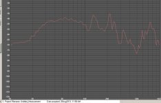
If using no lowpass on it you will need to pay attention to the port harmonics as they are easily audible if too close to the passband. I use a 6th order BP for my TV system ( built to match the TV stand) Here's a plot without any filters. Using pink noise you can easily hear the harmonics. Putting a 4th order 80Hz lowpass on it they disappear.
Attachments
the lengths for 4" diameter ports get shorter than a 5". also band-pass boxes are always tuned higher than bass reflex so that is helping you already.
as you know the port length doesn't have to be contained wholly inside the box, changing box dimensions and port tuning it's possible to use the sealed side to hide the lengths.
ADS uses simulated responses +cabin gains in their charts so any box simulators wont match up exactly.
'Unibox' an excel SS is good for playing around (designing ) with ports in band-pass boxes.
With such a closed back bandpass, you can avoid excursion protection of a high pass, and his phase shift/group delay.
But i recomand you measuring the real parameters of your speaker and to simulate. Harmonics (resonances with too long port) and chuffing (at high volume with too small port with ~~ >13m/s velocity) can be easily tweaked with hornresp for example.
If you can tweak to make the harmonics higher enough from you crossing point, you can filter this harmonics with a low pass set higher than your crossing point, so that it does not interact so much with phase at crossing point.
Does not neglect phase problem at crossing point, it can be such a pain, even in simulation ! (Only Akabak allow to simulate the full system, or hornresp in the special case of multiple-entry tool for synergy horns)
Last edited:
Hi,
Passive subwoofers are a complete nightmare when it comes to matching
to youir main speakers. Bandpass subwoofers never smoothly roll-off like
they do in simulations, they have bad midrange resonances you will hear.
An adjustable plate amplifier is the only sensible way to go. FWIW your
driver is far better suited to a vented box than sealed. 2cuft tuned to
30Hz (4" diameter x 16" length, 3" diameter x 8.5" length) is an idea.
Forget about passive, and bandpass, with or without a passive crossover.
rgds, sreten.
That why you need to simulate and shape principale resonances too, like akabak and hornresp allow to ^^Hi,
Bandpass subwoofers never smoothly roll-off like they do in simulations, they have bad midrange resonances you will hear.
...
Just to add, for simulation, you would need to take account inductance of the speaker. Such a low fs and powerful motor (qts=0,18), even with not so big xmax, has probably a lot of inductance, wich must be taken in account for it low pass effect (and again, it induced phase shift).
Why would any sane person take a driver with a wonderful 17 Hz resonance and stuff it into a tiny box that raises the cut-off to 81 Hz? You'd need a sub for your sub. Is lumber that expensive? Anybody have REW charts for something of that sort? Why do we see so much theory and so few test reports?
Those curves from the manufacturer are hokey... not to mention the 17 inch vent in a 16 inch box. Maybe ADS found a car without vents and a very small and very well sealed internal volume.
Ben
Those curves from the manufacturer are hokey... not to mention the 17 inch vent in a 16 inch box. Maybe ADS found a car without vents and a very small and very well sealed internal volume.
Ben
Last edited:
Why would any sane person take a driver with a wonderful 17 Hz resonance and stuff it into a tiny box that raises the cut-off to 81 Hz? You'd need a sub for your sub. Is lumber that expensive? Anybody have REW charts for something of that sort? Why do we see so much theory and so few test reports?
Those curves from the manufacturer are hokey... not to mention the 17 inch vent in a 16 inch box. Maybe ADS found a car without vents and a very small and very well sealed internal volume.
Ben
The completely sane engineers that presented this data sheet are taking into consideration the effect of car cabin gain and the great desire that some people will have to use the smallest possible enclosure. That's why the .6 cu ft sealed enclosure with F0 = 81 hz is there. It's not about the price of lumber, it has everything to do with people not wanting to use too much precious trunk space and having the dsp capability to get any kind of response curve they want.
Regardless of the box size, this driver is not made for sealed enclosures, especially if you don't have the massive cabin gain of a car. Even in an infinite baffle, the largest sealed box you can make, box qtc can't be more than driver qts, which is .18. That's a very small qtc and without significant room or cabin gain or extensive signal processing the F0 is going to be very high in ANY sealed enclosure size.
This is the basics of sealed box physics. Clearly the 17 hz fs isn't "wonderful" when you take the .18 qts into account and intend to use a sealed box of ANY size.
The theory is solid and there ARE plenty of test reports for all different kinds of drivers. Based on the theory, a lot of us know how the response is going to look without having to simulate or measure the results. Cabin gain will be a large factor and it's relatively unpredictable but it's not a complete unknown factor. The 2 pi sealed results in ANY box size are no mystery at all however.
I have a vintage ADS RS12 12" Dual voice coil. Got it from the car. I'm going to use it in home as a PASSIVE subwoofer, so the enclosure has been considered.
I remember that driver - might even have a CSR review of it in my magazine archives. The Qts was very low for 12" drivers back then and even for 12" drivers now.
If I remember correctly, it was positioned mainly for infinite baffle use.
For home audio use, I probably wouldn't use this driver. I'd Ebay it (you should get a decent price) and buy a more suitable driver instead. Or perhaps consider its use in a horn alignment.
I understand as people say the spec from the manufacturer may not seem to be 100% true with the real driver. IMHO, The reason may be the dressing up some data to made them "compatible" with their other components i.e. the mid/high drivers, the power amp, elec x-over, etc. to make them a "uniformly compatible set". For example, The real driver may have the real characteristic like this but in order to made them "genuinely this brand", they must be or should be tuned on that way to gain xyz things (warmth, smooth, color, etc.). But that won't be that bad at all because as a sense of those engineer, I believe they know how deep can they go.
Back to the old story, since I've posted the spec of the driver and asked for some advice to build the cabinet, I did not really want to make thing complicated but just want to build a simple enclosure that is in lining with the given specs from those the sane engineer of the manufacturer, because I know that the specs appeared to us may not be the 100% true but at least they are what the engineer wishing or intentionally to be.
Back to the old story, since I've posted the spec of the driver and asked for some advice to build the cabinet, I did not really want to make thing complicated but just want to build a simple enclosure that is in lining with the given specs from those the sane engineer of the manufacturer, because I know that the specs appeared to us may not be the 100% true but at least they are what the engineer wishing or intentionally to be.
- Status
- This old topic is closed. If you want to reopen this topic, contact a moderator using the "Report Post" button.
- Home
- Loudspeakers
- Subwoofers
- Bandpass build confusing!