Say I have a simple Vbe multiplier in a TO-92 package.
How is this attached to the heatsink, and is there an optimum placement in relation to the output transistor on the sink? I would assume being in close proximity to the metal tab on the output transistor would be good, but I usually assume wrong on these matters! Can it be a few inches away if layout seems to point that way? Also, if the opposite power transistor is on a separate sink, is there a reason to put the Vbe multiplier on one or the other? is it better for the power transistors on bothe halves to share a sink so they are more thermally coupled? So many questions!
Also, even though I would likely use a mica insulator on the power transistor, for sake of argument, lets say the heatsink is otherwise isolated from the circuit and I chose note to insolate the transistor tabe from the heatsink. Can I consider the case on a TO-92 type package to be sufficiently insolated to also be attached to said heatsink? Not something I really plan to do, just trying to expand my undertstanding.
I think that it is all irrelevant as long as you have "linear" relationship: Heat sink temperature-Vbe output voltage. You put it somewhere u like when it is cold, measure idle current, than run the amplifier till it become HOT, than you measure I idle again. If it remains the same, it is doing its job very well ") No need to complicate things.
No need to complicate things.
No need to complicate things.It helps to understand how it all works. If the output transistors run at a fixed bias voltage to give a given current then as the junction temperatures increase, so the characteristics change. In simple terms it mean that the output stage draws more current, gets hotter, draws still more current and so on. That results in destructive thermal runaway. So the vbe multiplier attemps to compensate by reducing the bias voltage in relation to temperature.
To work properly it has to sense the temperature as quickly as possible and that means mounting it as near as possible to the outputs. Both outputs should share the same heatsink so that both heat and cool the same.
A plastic T092 is just fine, the insulation would be in the high 100's if not low 1000's of volts.
Here's an old thread. Post #18 shows one way I have used in the past and there are examples of other members methods.
http://www.diyaudio.com/forums/soli...t-top-body-output-transistor.html#post1429206
Thanks guys.
Lets say I have a to-92 Vbe multiplier, and to-220 type output transistors. Any tried and true method for sticking them together that isn't permanent? I am still in the breadboard experimentation stage here, so I would like to avoid gluing parts together for now, although I suppose it wouldn't be a big deal.
Also, for this breadboard setup, I have 2 breadboards, one containing the power supply, and another with the amplifier circuitry. They are both mounted to a piece of 1x4 wood. I also have a separate piece of wood on which I have attached the heatsinks for the output stage, although I have yet to mount transistors on it.
This amp will be ~20 watts into 8 ohms. I was wondering how long I can have the leads from the amp breadboard to the power transistors be and still have decent stability. I will keep the individual wires separate, and will use maybe 22 gauge wire for this. I just want an operating amp that I can measure, scope, and experiment with.
I will be using mje340/50s for drivers. I'm digging up that data sheets right now, but if I bias them at, say, 20mA, will they require heatsinks of their own in this low powered amp? I have Cordell's book, and have reda his section on heatsinks and thermal resistance and what not. I'm not yet clear on how to find out how hot a particular transistor gets at a particular wattage, and how hot it should be allowed to get. I was going to go by touch for now.
I like the leach amp vbe multiplier where diodes are mounted on the heat sink. You then have the option of having two heatsinks for the output transistors.
This is what I did with my leach amp build. two diodes on each heatsink. Seemed thermally stable but I never did any tests as to how accurate the tracking was.
This is what I did with my leach amp build. two diodes on each heatsink. Seemed thermally stable but I never did any tests as to how accurate the tracking was.
Say I have a simple Vbe multiplier in a TO-92 package.
I like Andrew's idea of a SOT223 device, but haven't the dexterity to connect wires to the tiny critters. (Fine when they are lying flat on a PCB).
The problem with any heat sink mounted device is the thermal lag between the time and temperature.
Bob Cordell gave a great presentation for the NJ Audio Society on the beneits of the NJL devices. I have them on deck for a complete remake of a Crown DC-300.
Bias current goes through both devices and they tend to heat and cool the same. I drill a hole near the output device, put in some thermal grease and just stick the device in. That seems to hold it well enough for test purposes and probably forever if you have some small clip for the wires. There are about a dozen ways to do this.
Glue a sot23 to the collector lead where the lead exists the package.
Possibly as quick reacting as the diode as in the NJL package.
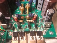
I vote for this idea. In fact, glueing is not required, just a dab of heat sink grease if you place them on the part of the PCB right under the collector/drain pin, like I did in this amp.
The devices marked by the yellow boxes, under the drain pin in the center of the TO-220 are SOT-323, or SOT-23 mini.
my SUPerb sounding little stereo amplifier module, complete with power supply, fault condition sensing logic control, and cascoded HEC driven mosfet output stages.
Attachments
Last edited:
Thanks guys.
Lets say I have a to-92 Vbe multiplier, and to-220 type output transistors. Any tried and true method for sticking them together that isn't permanent? I am still in the breadboard experimentation stage here, so I would like to avoid gluing parts together for now, although I suppose it wouldn't be a big deal.
Also, for this breadboard setup, I have 2 breadboards, one containing the power supply, and another with the amplifier circuitry. They are both mounted to a piece of 1x4 wood. I also have a separate piece of wood on which I have attached the heatsinks for the output stage, although I have yet to mount transistors on it.
This amp will be ~20 watts into 8 ohms. I was wondering how long I can have the leads from the amp breadboard to the power transistors be and still have decent stability. I will keep the individual wires separate, and will use maybe 22 gauge wire for this. I just want an operating amp that I can measure, scope, and experiment with.
I will be using mje340/50s for drivers. I'm digging up that data sheets right now, but if I bias them at, say, 20mA, will they require heatsinks of their own in this low powered amp? I have Cordell's book, and have reda his section on heatsinks and thermal resistance and what not. I'm not yet clear on how to find out how hot a particular transistor gets at a particular wattage, and how hot it should be allowed to get. I was going to go by touch for now.
20ma is perhaps a bit high for drivers. Something like 3 ma and using something like 330 ohm "emitter" resistors for the drivers might be better. No heat worries for the drivers like that in an experimental amp.
As you know, W=IxV and that applies to transistors. (Collector current x voltage across E and C)
If you can touch the metal tab for a couple of seconds then its fine. If it starts to sizzle water its to hot (although 100C is well within its continuous rating). It would reach that point at (I'm guessing) around 1.25 watts to give you a rough idea.
As to stability, you are just going to have to try it. The biggest issues in a breadboard experimental setup on an amp with a differential input stage comes down to the grounding. I can tell you that from years of experience. Using one strip on the breadboard as a ground causes problems.
You might find some interest here (although this isn't an amp with a differential input and so inherently more forgiving of poor layout)
http://www.diyaudio.com/forums/solid-state/126370-oscillograms-testing-why-layout-matters.html
For about 15 years, I've simply bolted the cheapest T0126 transistor I could find, on top of one EF output transistor - ever since I saw D Self's illustration of this, in fact. It's quick and simple to disassemble and is easy enough for a complete klutz to figure out and fix if need be. It's worth adding that it's not strictly necessary to use thermal grease with these either, as there is no significant heat loss other than via the leads. This applies to use with insulated flat packs like TO247, 264, 03P etc.
Sure , you can't just screw this assembly up super-tight with impunity. It needs care in the balance of torque which is sufficient to bring the transistor in full thermal contact with the sink but not crush the TO126 transistor. A large O.D. steel washer plus star lockwasher under the bolthead is a good idea, to distribute the force. If you want the ultimate performance, add an insulating washer before the TO126 transistor too, it may also aid with pressure distribution.
The benefits, as others have already said, are the speed and accuracy of bias. Just bolting the transistor to the heatsink is too slow and only applies yesterday's bias in terms of the signal's demand. There is still a delay and errors but they still lead to less distortion which can't be a bad thing in regard to "out of synch" bias. Why even use bias if the accuracy is unimportant to you?
Whilst I agree with the application of SMT assemblies as shown here and elsewhere, these are not easy to implement or troubleshoot for noobs, even if they are less likely to be a problem than the output transistors themselves. I guess if it was part of a pro. amplifier project and its PCB, this would be a technique worth encouraging.
@mooly:
Why specifically is a diff amp more susceptible to poor grounding on a breadboard?
For what its worth, I finally have a working specimen up and running on the breadboard. I actually can't believe it sounds as good as it does considering...
I have not trimmed any component leads. I basically have a forest of parts standing tall on their leads.
I just used two diodes in the rectifier, so its only half wave. That will be my next mod I think.
I Have the power supply on one breadboard, and the amp an another. My ground is basically one long strip. I did put all my ground connections "in order" if that makes any sense, but there is no star grounding at all.
I have probably 8 inch wires running to the power transitors which are on heatsinks bolted to a separate piece of wood. A few of my breadboard jumpers are kinda long and loopy too.
There is a SMALL amount of 60 htz hum, but it is almost unoticable when the ampo is quite, and absolutely unnoticeable when I play music.
My Vbe spreader is not coupled to the sink or a transistor or anything yet. No thermal runaway, or even excessive heat in the o.p. transistrors, but they are 3055/2955 that are capable of a lot more than I'm currently throwing at them
I sorta just guessed my miller cap a 300pf, but I haven't measured my IPS current in awhile, and there has been many changes since then. Until I measure the tail current, I have no idea what my slewrate/stability are. That's also next.
I did a current mirror on the input stage. I hade terrible DC offset (it was 200mA and climbing before I shut it off), but the mirror instantly brought down to 2 or three mA. I was surprised the resistor loaded version was so out of wack though. That normal? Actually, I initially had my IPS undegenerated, and had no offset problems (measured at the output). It was when I added 10x degeneration that the offset crept in. Does this make sense, or is my mirror hiding a deeper issue?
Anyway, the thing sounds surprisingly good. Better than a pair of powered m-audio monitors I was using on my PC.
Oh, and I have been playing MP3s through it, so who knows what proper source material would sound like.
To sum it up, this amp sounds way better than I though it would considering all I have mentioned. Looking forward to poking and prodding so I can learn more!
Actually, when I wrote that post, my iPod was unplugged from the cord, so the cord was just one big antenna. Plugged it back in, and there is zero hum.
Did I just get lucky, or is it because of my low wattage.
Oh, and my speakers a 6 ohms, and since I have only one channel, they are currently running in parallel. Should be almost 40 watts into 3 ohms, which is probably a pretty hard load to drive. Tis is my first solid state amp, and first hi fi amp. I am blown away at how good such a crude setup sounds. Can't wait to hear what "doing it right" will sound like!
For about 15 years, I've simply bolted the cheapest T0126 transistor I could find, on top of one EF output transistor - ever since I saw D Self's illustration of this, in fact. It's quick and simple to disassemble and is easy enough for a complete klutz to figure out and fix if need be. It's worth adding that it's not strictly necessary to use thermal grease with these either, as there is no significant heat loss other than via the leads. This applies to use with insulated flat packs like TO247, 264, 03P etc.
I did it many times as well. But as I heard one of my amplifier, I found strange distorted sound somtimes. As I measured the bias, it was totally cut after some loud music parts.
So I get heavily overcompensated system. Now I think, that some controlled overbias (or controlled thermal runaway) sounds better. Now I simply put TO-126 device to the heatsink.
Another point of view (little offtopic) high hfe types are better for Vbe multiplier. I use 2SC3503E of F for this purposes. Maybe TO-92 devices such as BC550C with hfe>500 can be even better.
Sajti

Sounds like your learning quickly and having fun
The diff amp is susceptible to problems on the breadboard simple because of the small but finite resistance of the contact strip.
A good test of any lash up is to check the output voltage doesn't change at all as you connect a load of say 4 or 8 ohms to ground. Set for say 8 volts peak to peak output and then dab the load resistor on and off the output. There should be zero change in level.
On a breadboard lash up you may find the level increases or decreases. All point to problems with the critical ground nodes of the circuit and how they are returned.
- Status
- This old topic is closed. If you want to reopen this topic, contact a moderator using the "Report Post" button.
- Home
- Amplifiers
- Solid State
- attaching Vbe multiplier to heatsink