I promised to show my measurements on the Large Bybee device on April 1st which I have declared open Bybee day!
First my two test setups.
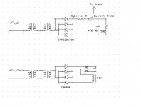
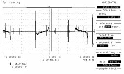
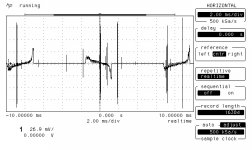
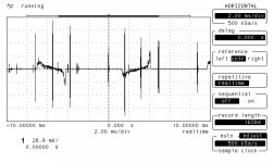
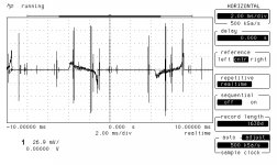
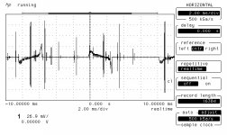
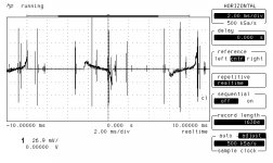
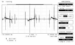
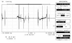
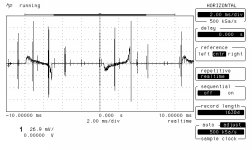
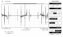
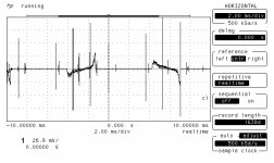
One is using a toroidal transformer to feed a bridge rectifier that was loaded by a 500 ohm resistor and 460 uF capacitor. The device under test was either a Bybee or a thin piece of wire that measured .025 ohms the same as the Bybee. A current probe was placed after the device under test.
I used my line noise generator to add lots of noise spikes to the AC line.
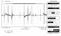
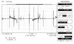
Attached are the schematics, a picture of the first test setup and six of the test runs.
First my two test setups.
One is using a toroidal transformer to feed a bridge rectifier that was loaded by a 500 ohm resistor and 460 uF capacitor. The device under test was either a Bybee or a thin piece of wire that measured .025 ohms the same as the Bybee. A current probe was placed after the device under test.
I used my line noise generator to add lots of noise spikes to the AC line.
Attached are the schematics, a picture of the first test setup and six of the test runs.
Attachments
-
 Power Supply Test Set Up.jpg69.2 KB · Views: 380
 -
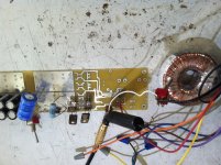 photo.jpg752.7 KB · Views: 366
 -
 NOBEE003J.jpg77.2 KB · Views: 81
 -
 BYBEE03J.jpg76.9 KB · Views: 83
 -
 NOBEE002J.jpg76.7 KB · Views: 117
 -
 NOBEE001J.jpg78 KB · Views: 358
 -
 BYBEE02J.jpg75.8 KB · Views: 361
 -
 BYBEE01J.jpg75.8 KB · Views: 364
 -
 BYBEE09J.jpg77.2 KB · Views: 73
 -
 NOBEE009J.jpg77.9 KB · Views: 74
Last edited:
More test runs.
Attachments
-
 NOBEE008J.jpg78.2 KB · Views: 38
 -
 BYBEE08J.jpg77.3 KB · Views: 33
 -
 NOBEE007J.jpg75.6 KB · Views: 42
 -
 BYBEE07J.jpg76.6 KB · Views: 44
 -
 NOBEE006J.jpg78.2 KB · Views: 40
 -
 BYBEE06J.jpg76.8 KB · Views: 40
 -
 NOBEE005J.jpg77.8 KB · Views: 50
 -
 BYBEE05J.jpg78 KB · Views: 50
 -
 NOBEE004J.jpg76.3 KB · Views: 59
 -
 BYBEE04J.jpg76.6 KB · Views: 79
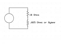
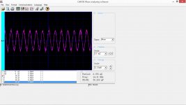
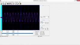
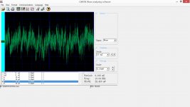
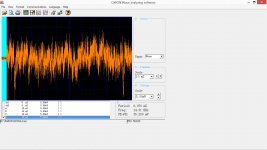
Now the second test was simple I used a power amplifier to put a signal through a 10 Ohm resistor and then into the device under test, either the large Bybee or a .025 ohm resistor. The traces shown are the voltages across the device under test.
The schematic is attached as are the results for a sine wave or a pink noise excitation source.
The schematic is attached as are the results for a sine wave or a pink noise excitation source.
Attachments
Last edited:
Hi Ed.Now the second test was simple I used a power amplifier to put a signal through a 10 Ohm resistor and then into the device under test, either the large Bybee or a .025 ohm resistor. The traces shown are the voltages across the device under test.
The schematic is attached as are the results for a sine wave or a pink noise excitation source.
Any chance of redoing this sine/PN test with the probe across the load resistor and using recorded PN and sine waveforms ?.
Dan.
I now have it on good authority that we should should be able to decipher some info and draw conclusions from what Ed has provided.
So many questions... What is the relay in the first schematic for? What is the vertical scale of the first bunches of "results"? I suppose it doesn't matter as long as it is the same.
I guess my expectation bias is showing. I would not expect to hear any difference between a Bybee and a resistor (or even no resistor) and I do not see any difference. I expect I wouldn't hear a difference either.
I hope you're going to try harder Simon. I'd like to see some zoom shots on some of those colored comparisons. Plus we need to see comparisons on the same plot or it's impossible to tell if it works except to say the device doesn't do huge changes.
What I don't want to see is half-assed attempts. Why? because I can easily hear the difference between using them and not on AC power distribution. I'd love to see what's happening, since it appears like nothing yet it's very audible.
I also don't understand the relay, except using it to introduce noise? That doesn't make sense. The control should be identical and just replace the bybee with an equivalent resistor or nothing.
Lastly, April 1st? Are you going to just make a joke?
Last edited:
Now the second test was simple
I think it will be MORE relevant (don't anyone think so?) if the Bybee is in the supply line (like Test1), then an amplifier and the the probe on the load (like Test2).
I think it will be MORE relevant (don't anyone think so?) if the Bybee is in the supply line (like Test1), then an amplifier and the the probe on the load (like Test2).
I'd rather see it on the AC line side.
And let's try to keep civil and help Ed make a good comparison.
Knowing how things can be audible, I believe that whatever (RCL) inside the Bybee, it could be very audible...
But with this experiment, interpretation of the result could be very difficult if the interpreter has never heard differences, unless he has an idea of what to look for.
But with this experiment, interpretation of the result could be very difficult if the interpreter has never heard differences, unless he has an idea of what to look for.
Knowing how things can be audible, I believe that whatever (RCL) inside the Bybee, it could be very audible...
But with this experiment, interpretation of the result could be very difficult if the interpreter has never heard differences, unless he has an idea of what to look for.
JC (Curl, not Christ) posted a small snippet of a difference that looked very minor, but was measurable with proper equipment.
To see the difference here one might need a distortion amplifier. I'm not sure you need a noise generator. You could just measure simultaneously across a resistor and across a bybee, both passing the AC to your appliance. Compare both at varying time intervals at peak phase areas and mid slope.
That's my guess, I'm not experienced in testing as much as others here. The initial testing is like trying to merge two separate graphs visually as one, that are compressed visually so it's like looking at a 4 minute long song in the span of two inches.
One can take the data plots enlarge them all by the same amount and either print them on clear film or use a light table to do comparisons the old fashioned way.
To enlarge under windows hit control while turning the mouse wheel. Then hit print screen and paste the result into just about anything you can print.
Or you can just use calipers to compare amplitude features.
You are welcome to interpret the data any way you like.
Circuit theory allows for resistance, inductance and capacitance. Does the device under test behave the same as the comparison resistor?
It measures .025 ohms and .00002 mH on my Digibridge.
Circuit theory allows for resistance, inductance and capacitance. Does the device under test behave the same as the comparison resistor?
It measures .025 ohms and .00002 mH on my Digibridge.
How about capacitance? The reason I mentioned that it could be more relevant to measure the output at load level (and the DUT on the power supply) is because that is how we/I hear the difference in real life (through the speaker)...
From knowing exactly what I usually hear, here is a hint: I'm not interested in AMPLITUDE at all...
You can't prove anything rigorously enough for audiophiles - and it falls under the "no such thing as bad PR" rules and will just advertise the product.
The Definitive Bybee Experiment - Page 13 - Power, Cables & Electronics - StereoNET
The Definitive Bybee Experiment - Page 13 - Power, Cables & Electronics - StereoNET
I know I can hear a difference, why must you obfuscate this with data and facts?
That's the way how scientists and engineers think and work so they can come up with "solutions" you access in your everyday life.
I have background in Physics, but often I have to rely on my ears, trying different DUTs and judge by ears simply because I don't understand why and how they can sound different. If I know for sure, I will have not wasted my time...
- Status
- Not open for further replies.
- Home
- Member Areas
- The Lounge
- April 1 Bybees !