This was my first DIY from scratch electronics project ever and it got finished without a single major problem. I completed the amp after 4 hours of non stop soldering and had it singing within an hour after that. I didn't even bother with the rigorous testing phase suggested in the instructions after you finish the amp, I just hooked it straight up.
The amp sounds great, but I'm not sure if I'm getting all the power I'm supposed to be. I only measure 14v across the terminals of my 8ohm mains before heavy clipping sets in. I'm not sure I have the math right but that should be 14v * (14v/8ohm ) = 24.5watts.
I'm using 28v rails, so I'm only getting half of what I should be getting correct?
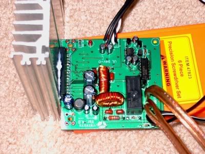
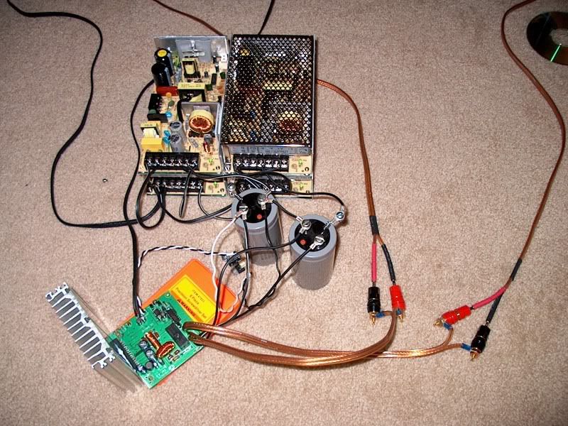
Here's some pics of the board and the test setup.


use a scope, you cannot measure a true RMS signal with a Voltmeter. They often are not accurate at most frequencies.
I was using a true RMS voltmeter and playing a sine of 1k if that helps any. I don't own a scope so I am limited to using my meter.
try again using a non-switching power supply, i know for a fact that some SMPSU's can affect the stability and performance of class-D and class-T amp's..
The switching supplies are all I have unfortunately. The voltage is rock stable a +-28v and the supplies have 12 amps of current behind them. There is also a dangerous amount of bulk caps there at a total of 108,000uf.
I don't see an issue with the supply voltage and current causing any problems, unless you were referring to switching noise from the supplies causing problems. If so, is there any way to filter it out of the output?
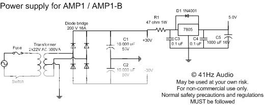
You shouldn't connect ground from the big elektrolyt to the 5V stabilizer. Read the instructions from Jan on this. Big ground loop the way you did it.
Actually its wired exactly the way Jan shows it in his schematic for a power supply. As you can see in the pic, both grounds are in fact tied together.

It doesn't matter anyways, as I have since switched to using a separate transformer for the +5v. The LM705 dumping the other 23v as heat was enough to burn my finger when I touched it, that was the only reason for the switch.
curious power problem
If you do not have a scope how are you telling when you reach clipping? Are you using speakers for the load? If you are you have just measured their power handling abilities. If not there must be a flaw in how you are determining the clip point. I don't have a clue how to tell without a scope unless something rather elaborate is built to compare input to output.
I sure wouldn’t recommend running a full power sine wave into a speaker. The potential for damage is too great to;
1) hurt your hearing
2) hurt your speakers
3) hurt your wife’s or significant others hearing
3) hurt your relationship with your neighbors.
4) make your cat/dog run and hide
5) break glass ware on the shelf
Roger
1) I was wearing ear plugs, I value my hearing.
2) The test speaker would be no big loss if blown.
3) The Mrs. works days and I work nights, so she wasn't home.
3) My closest neighbors are quite some distance away.
4) My only pet is a fish, and he has no ears that I can see.
5) Breaking glass with sound? now that would just be fun.
When I said clipping, I meant heavy audible clipping. Your right, I have no way to see when the actual clipping begins, but anyone who owns a Sonic Impact amp can hear what I'm talking about for themselves by turning the amp up all the way. Its a very distinct sawtooth type of sound.
I have tried lower frequencies, but the clipping just seems to set in a little sooner the lower I go. I was also using an ammeter to verify the resistance of the load by E/I=R.
missing power
Let’s look at this a little. If you have 28 volt rails with a non bridged amp this means you have about 26 volts peak before the outputs can’t go any further. .707 X 26 = 18.38 volts RMS, 18.38/8ohms = 2.3 amps RMS, 2.3 X 18.38 = 42.27 W RMS. This is a reasonable number as the chip is rated for 100w into 4 ohms. This would be 50w into 8ohms. With a full +/- 30 volts this looks right. These power ratings are at 1% distortion. What this means is a 1% average for the whole sine wave. This in turn means the peaks are probably 10% distorted while the rest of the sine wave is clean. I am guessing here as to actual values but ball park should do. As you noted this kind of clipping is very clearly heard so you probably are stopping when the peaks are only .5 – 1% distorted. I would think this could easily drop the power down to the 25w range. It all is a question of when you stop turning the control up. There are way too many variables here to be worried about your results. Just turning it up a little further would be full rated power. Remember a 1db change is about as small as we can reliably hear and 3db sounds only a little bit louder but is twice the power.
Roger
- Status
- This old topic is closed. If you want to reopen this topic, contact a moderator using the "Report Post" button.
- Home
- Amplifiers
- Class D
- AMP1-B: why only 25 watts @8ohms?