greetings,
i have been to many sites trying to understand the nuts and bolts of grounding schemes for amplifiers. i understand the words but it doesn't translate when i go to wire my amp. can someone tell me exactly which part of the circuit goes to what part of the overall ground and where to physically locate these???
here's what i have so far:
-ac earth to chassis, along with a ground to the negative input for each channel.
-tranny and filter caps ganged and attached to another part of the chassis.
that's it so far. what about star grounding for the signal, i.e. pcb.? where do i put that?
do i need to run a wire connecting the tranny/cap ground spot to the mains chassis earth?

thanks for any input,
p.s.
i've been to ESP site, Promitheus, and several other amp sites so far.
cheers,
scott
i have been to many sites trying to understand the nuts and bolts of grounding schemes for amplifiers. i understand the words but it doesn't translate when i go to wire my amp. can someone tell me exactly which part of the circuit goes to what part of the overall ground and where to physically locate these???
here's what i have so far:
-ac earth to chassis, along with a ground to the negative input for each channel.
-tranny and filter caps ganged and attached to another part of the chassis.
that's it so far. what about star grounding for the signal, i.e. pcb.? where do i put that?
do i need to run a wire connecting the tranny/cap ground spot to the mains chassis earth?
thanks for any input,
p.s.
i've been to ESP site, Promitheus, and several other amp sites so far.
cheers,
scott
hi
as far as my understanding some folks run 2 type of grounds.
1 elctrical that normally is tied to the negative side of power supplys caps an the other
the other is the audio path ground. (i am not very clear with these)
another type of grounding is called "star grounding"
from one point all groundings are tied to this point .
i hope that this info will help you
richt
Only very few commercial amps do actually have a ground connection to the power cord.
Grounding problems is one very common because the normal interconnects between audio amps and sources do not follow the rules of starshaped grounding and ground loop prevention.
Connecting for instance a cd stereo to an amp by a normal interconnect makes two ground paths instead of a single one.
This is a ground loop.
In principle it would be better to disconnect one of the shields at the cd side (the shield is still grounded by the amp).
Also the connection and quality of the shielding of cheap interconnects often is terrible.
The basic concept is that wire has resistance, however small. If two currents share a wire there will be a voltage drop along the wire that is related to the sum of the currents. Problems arise when this sum voltage is not desired or not anticipated by the designer. To avoid it, two separate wires should be used, one for each current flow. If a wire must be shared then use very low resistance wire or braid.
Taken to the limit, you choose some point in your amp's box - and run every 0V connection from every point in your circuit/psu/input and output cables to this point using separate wires. The point should be as compact as possible - not a length of wire or a ground plane. This ensures that two circuit's currents will not share the same wire and inadvertently create a sum voltage drop across the wire. Obviously, choosing the location of this point to minimize the length of the wires is advisable.
This is particularly important in power amps because it is surprisingly easy to end up mixing the speaker current with the input signal current if your are not careful OR adding the speaker current to the psu rails. These sort of things can result in oscillation or a mysterious mains hum at the speaker. If an amp is wired properly and the basic circuit is sound you should hear none or very, very little hum at the speaker even with your ear stuffed into the woofer. With no source connected, audible mains hum at the speaker is a dead give-away that something is wrong.
http://www.diyaudio.com/forums/attachment.php?s=&postid=498232&stamp=1098624936
If there is 3 different GNDs in an amp:
- signal GND from the RCA
- small PS gnd (for input and 2nd stages)
- big PS gnd (for the output stage)
Qs:
- where should I connect the gnd points from the amp ?
(from current sources, dc servo, feedback resistor, zobel, etc...)
- what is the ideal method to connect these 3 gnds together ?
(through resistors, or directly with low resitance, or with RC, ... ?)
I know the well known solutions, but maybe there are some other alternatives...?!
Thx!
Hi,
as I see it here are four grounds.
Safety, analogue power, signal and digital (if fitted).
The mains incomer earth lead MUST be securely and permanently fixed to conductive chassis. This must NEVER be removed, not even for testing. If there is no conductive chassis you need to build to double insulated standard (I don't know how). Add a second nut holding captive a spare solder tag.
The power ground has the power supply common, Speaker return, output Zobel, main decoupling on PCB, relays, spare tag. The power supply common should have smoothing caps and transformer common connected then run a wire from PSU common to Power ground. This wire can be very short, even a short bolt achieves the same effect. KEEP the PSU charging PULSES out of the Power ground.
The signal ground has input ground, NFB return, input cascode and other ground reference, RCA/XLR ground, input RF filter, low current CCS grounds, spare tag.
The three/four grounds can be connected at or near the power ground. Location is less important.
By keeping the ground system separate you can now interconnect in various ways.
1. Connect all directly to each other.
2. Connect power and signal directly and leave safety disconnected.
3. Connect power and safety and use a resistor to connect signal.
4. Connect an isolating network from safety to power ground and connect signal with either a resistor or directly.
The isolating Network can consist of any combination of the following:-resistor, antiparallel diode pair, capacitor, ground lift switch.
Version 4. mimics version 2. at low frequency but becomes version 1. when the switch is closed.
version 2. keeps complete isolation between chassis and amplifier and ancilliaries.
The main point is to keep all four grounds separate until you are ready to interconnect them.
A star ground is a method of making each ground. Every ground attachment comes to the star ground on it's own wire or PCB track and all the connections are coupled together at one point or star. This can be used for the power and for the signal.
Hi Andrew, and first of all thx for your reply!
> as I see it here are four grounds.
This is not my concrete amp, just an example, to reference to.
The point is, that it has separate PSs for the class A 1st and 2nd
stages and for the class B output stage with high currents.
> Safety, analogue power, signal and digital (if fitted).
For now lets forget the safety earth, and all of the metal chassis.
There is a source device (DAC) with two wires (GND + signal).
So there we have our 3 GNDs.
> output Zobel
Otherwise where should I place the Zobel, someone sais directly to the PCB,
others say near to the speaker terminals, cause then it protects the whole
PCB and the feedback from the high freq noise coming from the speajer cable.
> KEEP the PSU charging PULSES out of the Power ground.
So that means, there should be a whick short wire between the two caps,
and the starGNDpoint should be on a spur in the middle on this wire ?
> The signal ground has input ground, NFB return, input cascode
> and other ground reference, RCA/XLR ground, input RF filter,
> low current CCS grounds, spare tag.
Ok, so every GND from the 1st and 2nd stages should be go to the signal GND ?
Or there must be 2 star on the PCB, a signal-GND for the input-GND and for the
feedback, and an other low-current one for the rest, like CCS, DC servo, etc ?
Or there is 2 group of GNDs, cause a DC servo is also a signal "stage", and
maybe therefore an clean GND is important, but for a CCS maybe its no so
important, and the GND can be noisy and floating ?
And if I have 2 different GNDs on the PCB after this, where should I connect
them, on the PCB, or at the near of the main GND starpoint ?
And what about the two PS GND, its possible two connect their GNDs through a
resistor, like between the signal-GND and the PS GND sometime, or its important
to connect them with a low impedance short thick wire ?
Hi,
I recommend that the output Zobel be fitted to the speaker output terminals.
If fitted to the amp PCB then it should NOT return to the signal ground. Some designs oscillate if the zobel is connected on the PCB.
The PSU common should have all the PSU commons together. Do not connect your main power ground to the middle of this common wire. Instead run a wire from the common to a remote power ground.
The signal grounds can all be connected on the PCB. This should not include any decoupling from the supply rails.
what is this, stereo or +ve Pground & -ve Pground?what about the two PS GND
Hi all,
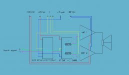
I have also a problem these days with grounding. I've made a bridged subwoofer amp. The amp exist of two amps, one sub filter / controller and a assymetry to symmetry converter.
But I have problems with humm. I tried already something, and it helped me a bit, but it isn't perfect yet.
Can you guys help me out.
I 've attached a sheme, what I think looks good. Any comments??
Greetz
Ben
Attachments
> > what about the two PS GND
> what is this, stereo or +ve Pground & -ve Pground?
No, now, its just one side, nothing stereo. It will be an other story later.
Thats why I showed you that schematic, because it has 2 different PS.
One for the 1st and 2nd stages, and an other one for the output stage.
It means separate sec, doides, caps, etc. So what are the alternatives
two connect their 2 GND together ? It is necessary to wire them directly
with wire, or there are more possibilities, for example with resistor,
or through capacitor, etc ? What kind of current will flow between this 2 point ?
A constant DC current, or its just an equalization wire, and mainly there is
no current on it ? Cause then maybe a cap is also enough to achieve this ?
An other similar question: what current flows between the two caps in a symetrical PS ?
Its constatnt, or it fluctuates with the cap-charging currents ?
And again what is the base concept to group the GND points on a PCB ?
Which GND-point where should be routed to ?
CCSs to the small-PS-GND and everything else signal related subcircuits'
GND to the local PCB signal GND-star, what goes further to the main PSs GND ?
To minimise bad effects of the charging pulses, transformers, diode bridges and reservoir caps should have the shortest connexions as possible between them. Most commercial amplifiers have not.
BENSEN
Looking at your schematics, it may interest you to be aware that Douglas Self recommends that the positive and negative wires (from your +/- 48 V) supplying current to the power amplifers should run close parallel to each other. As it is a bridge amplifier, I think that it would be beneficial to have a single wire, instead of two, from each reservoir cap to supply both parts of the amplifier.
I bring back this old thread since there's a puzzle to which i can't seem to find any explanation (good enough). Attached are schematics of few simple one-transistor amplifier circuits. A good procedure is to separate signal and power grounds from each other but the question is which is which?
With my logic, the supply filter capacitor ground points (1 & 5) belong to power ground and all emitter resistor grounding points (3, 7 & 10) belong to signal ground, as well as the emitter bypassing (4). Is this correct? How about the other ground points that are related to bias set? What are the common procedures?
Teemu K
Attachments
Hi Cortez,
just connect all the power grounds together.
If each PSU is run from it's own transformer then by definition all of them are isolated from each other and from ground and from safety earth.
You decide where you want the reference for each. Most would want them all referenced to zero volts, this is your power ground reference.
Another different example.
PSU 1 is 50Vdc.
PSU 2 is 10Vdc.
You can stack the two supplies to give 50Vdc and 60Vdc or 10Vdc and 60Vdc.
Or you can parallel connect them to give 10Vdc and 50Vdc.
There is an exception to the definition.
There exists in all electronics a finite insulation level. The theoretically isolated transformers are affected by very small leakage currents. I would expect them to be no higher than a few pA.
The current that could flow between your PSU grounds is ZERO +- leakage current. Ignore it for all normal amplifier duties even when you strive for -120db noise levels.
Hi !
> just connect all the power grounds together
Ok. So there is nothing better solution, with R or RC, etc ?
Otherwise with the separation alternatives I just wanted to protect the different
subcircuits and PSs from each other, to reduce static and dynamic noises.
> The theoretically isolated transformers are affected by very small leakage currents.
Capacitive AC currents, if I'am right.
So this current can flow through the signal current on the ground
wire between the source and the amp ?
And where the currents are flowing from the GND points like the DC servo, feedback
resistor, CCS, etc back to the signal source (DAC), or to the main PS GND star point ?
Thx !
> just connect all the power grounds together
Ok.
So there is nothing better solution, with R or RC, etc ?Otherwise with the separation alternatives I just wanted to protect the different
subcircuits and PSs from each other, to reduce static and dynamic noises.
> The theoretically isolated transformers are affected by very small leakage currents.
Capacitive AC currents, if I'am right.
So this current can flow through the signal current on the ground
wire between the source and the amp ?
And where the currents are flowing from the GND points like the DC servo, feedback
resistor, CCS, etc back to the signal source (DAC), or to the main PS GND star point ?
Thx !
Hi Cortez,
keep all the power returns on the power ground. Then no power currents or power leakage currents can contaminate the clean (signal) ground.
That's my philosophy, keep the four grounds separate and only connect them by the recommended alternatives I gave you way back.
keep all the power returns on the power ground. Then no power currents or power leakage currents can contaminate the clean (signal) ground.
That's my philosophy, keep the four grounds separate and only connect them by the recommended alternatives I gave you way back.
teemuk said:With my logic, the supply filter capacitor ground points (1 & 5) belong to power ground and all emitter resistor grounding points (3, 7 & 10) belong to signal ground, as well as the emitter bypassing (4). Is this correct? How about the other ground points that are related to bias set? What are the common procedures?
Teemu K
Hi
maybe not exacly answer for you question:
Once I read that this third way of biasing gives the lowest noise (not the noise from power supply, but general niose from biasing resistors).
 Smash if advice was stupid...
Hi,
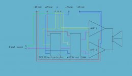
I've tried alot of configurations last week. But none of them seemed to have a good result for the humming problem. Sometimes the humm dissappeared, but when I touched something it started humming again.
Those grounding issues are a real pain in the ***! It's frustrating.
I've drawn an other configuration, after I've red a dozen or so, threads about these problems.
What do you think of this? I have to trie this tomorrow.
Greetz
Ben
Attachments
- Status
- This old topic is closed. If you want to reopen this topic, contact a moderator using the "Report Post" button.
- Home
- Amplifiers
- Solid State
- amp grounding schemes