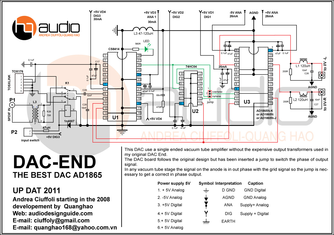
One thing that jumps out is that your schematic does not show any provision made to reset the CS8414 DIR chip upon power up. While I've not worked with the CS8414, it seems you may be experiencing some sort of initialization problem with it. See page 36 of the CS8414 datasheet for guidance on how to actively reset the chip.
Does this mean that the "reset" should allways be connected to 2v as in the page 36?
No. Unfortunately, a proper reset circuit would be much more complicated than that. You would need to redesign the board to include a quad 'OR' gate chip plus a reset supervisor chip.
Let's look at some less problematic possibilities. First, let's assume (not really safe to do) that Andrea has not experienced any reset related problems with this design despite his ignoring the reset handling. What then might be causing your trouble? One possibility is that there is power supply noise spikes during power up. Therefore, the first thing I would try is to bypass L3 with a short length of wire. Inductors intended to isolate analog and digital grounds are controversial. If that doesn't solve your problem, the design or implementation of the power supplies (not shown) may be at fault.
In addition, I would contact Andrea to see if he has before experienced this problem with his design.
Tried it with L3 shorted and there was no sound what so ever,the led was light all the time.
However Andrea Cuiffoli doesnt seem to be on DIY audio so I don´t know how to get in contact with him.
I found this:
S/PDIF Digital to Analogue Converter
it has an automatic reset switch,maybe I could try that.
I have the recomended shunt PSU on the original pcb so that shouldn´t be the problem.
However Andrea Cuiffoli doesnt seem to be on DIY audio so I don´t know how to get in contact with him.
I found this:
S/PDIF Digital to Analogue Converter
it has an automatic reset switch,maybe I could try that.
I have the recomended shunt PSU on the original pcb so that shouldn´t be the problem.
Tried it with L3 shorted and there was no sound what so ever,the led was light all the time.
I just noticed that the schematic has two differnt components identified as L3. One is the choke connecting analog and digital ground together, while the other is the S/PDIF input transformer. Just so that we're clear, it was the ground to ground choke you shorted out, yes?
Yes it was the ground L3.
Alright. You can try the simple manual reset circuit shown on the ESP site. However, you will need to make a few minor circuit modifications to Andrea's design, in addition to mounting the reset pushbutton somewhere.
To reset the CS8414, pins 17, 18, 23 and 24 all need to be simultaneously brought high for a moment. Your schematic shows pins 18 and 24 already tied high, so that means you only need to bring pins 17 and 23 momentarily high, and then those two pins should be brought back low. To do this you will need to un-tie pins 17 and 23 from ground and wire them so that they will be pulled high by pressing the reset button. Releasing the reset button then should allow those pins to be pulled low by a resistor, just as is shown in the ESP site circuit.
I got an answer from Quanghao:
http://www.diyaudio.com/forums/quan...-dac-end-best-dac-ad1865-updat-2011-a-22.html
A couple of days ago I ordered a new CS8414 if that doesn`t work I will try the reset schema.
http://www.diyaudio.com/forums/quan...-dac-end-best-dac-ad1865-updat-2011-a-22.html
A couple of days ago I ordered a new CS8414 if that doesn`t work I will try the reset schema.
Today I inserted the new CS8414 and it seems to work as it should..hopefully it will continue that way..
Glad, to hear that.
- Status
- This old topic is closed. If you want to reopen this topic, contact a moderator using the "Report Post" button.
- Home
- Source & Line
- Digital Line Level
- AD1865 DAC trouble