I have just completed the third version of an LM1875 amp on the QK50 pcb. I hope my experience so far will assist and encourage any other novices to try their hand at amp building.
I am using the power supply from chipamp.com with an Avel 250VA 18v trafo. I have so far played only one amp at a time, so all my observations relate to only monaural sound. The entire amp is mounted on a 2x6 board with no enclosure yet, but a decently sized, finned aluminum heatsink. There is a 2.5 amp slo-blo fuse between the trafo and psu board. The power supply wires to the amp board enter perpendicularly from a height of about 3 inches, as suggested by the NS Application Hints.
The source is a Marantz SA11-S1 SACD player, run balanced into a Sonic Euphoria passive preamp, through which the fixed line level signal is passed into my basement workshop via single-ended IC's to a Richard Lee passive preamp with shunt style volume control. The speaker I am using is a homemade two-way with output limited below 60hz, but very accurate above that. I do not enjoy hyper detail, and my entire system is biased toward smooth and spacious reproduction.
The first amp was built completely stock as it arrived from Quality Kits with carbon resistors and mostly cheap electrolytic caps with only one polyester cap for the zobel. I was happy that the thing worked perfectly right from the start, but I didn't like the etched high frequencies. Oh, there was detail alright, but it almost hurt my ears. DC offset was under 10mv, and hum and noise were well below the signal, almost completely inaudible. Neither the chip nor the heatsink got more than slightly warm.
Thanks to the posters here who have experimented with the LM1875 and shared their insights, I figured that I should reduce the gain to try to smooth out the highs. I replaced the 180k feedback resistor with 150k to lower the gain from 19 to 16, and that version was much more musical. Highs maintained great definition, but without the painful etching. Midrange also fleshed out and became somewhat more layered, even in mono.
I ordered a bunch of better quality parts (all the same values as the original kit except for the 150K) such as metal film resistors, all Panny FM electrolytics, and some polypro caps where they would easily fit the board, and built a second amp fresh with those. This amp is better yet, with real air in the highs and mids, and excellent smoothness to the highs. Almost all the harshness is gone: piano sounds a lot like piano, and cymbals have a 3D sheen. Again, this is all in mono.
Now I'm ready to tweak some more, and I would appreciate suggestions from those of you who have already gone beyond this point. One poster promotes battery power, but I would prefer to stay with the unregulated snubber supply or something equally practical. I don't want to engage in large scale circuit redesign, but would prefer to optimize performance through careful parts selection and valuation.
I'm considering buying a pair of smaller trannies to reduce the unregulated voltage from 18v to 15v and make a pair of monoblocks. The use of these amps will ultimately be the high frequencies of a tri-amp (or mids and highs of a bi-amp) system, so I wouldn't mind a higher low freq cutoff for the amp if that would improve performance in the upper range, but I don't know how to determine which component values to achieve that.
Any suggestions or additions are appreciated.
Peace,
Tom E
Your probably referring to my posts on the LM1875 amps, and yes I really feel this amp sings in the musical sense on 12v battery, and I have tried all the others except a fully regulated/snubbered supply, (i have tried a straight snubbered supply). I have also tried 24v battery supplies but somehow it just wasn't as sweet. I still feel the ideal voltage is about 16V but this is hard to get without going down a regulated route.
As for other tweaks there are a few things you could try.
Getting the small bypass caps right on the pins, and I means just where they exit from the package helps stability and hence sound, the only risk is getting the pin too hot during the solder process though I have not had any problems.
Going to battery power seems to mean that you have less problems in using higher value caps at the pins, typically these are 1000uf and anything greater starts to kill the highs, but with battery supplies this seems to be a non issue, 3200uf works well. However in my application which is not unlike yours ( I am not driving the lower bass) I use 100uf at the pins and 3200uf a couple of inches out from the chips and these are snubbered.
A lot of argument is made about short signal paths (pro and con) in my experience it does make a difference, but of course using a PCB kind of locks you in, my best sounding amps are all point to point wired and very small. It doesn't hurt to put the feedback resistor at the pins and a SMD type works well here.
Keeping your power supplies wiring well away from the inputs, coming in perpendicular if possible helps keep things sweet.
Star grounding is very important as well, but once again with a PCB this is often hard to really achieve perfectly.
Really good shielding of the circuit can help, I have actually built little copper coffins to over the boards and even put extra ground planes underneath the boards.
On the whole I think the 1875 really benefits from careful attention to detail, anything you do to make its power supply cleaner and the circuit more stable will reap dividends. I think there is a tendency for folks to get all hyped up on different circuits etc but really I think the guys at Nat Semi have done a pretty good job working out a good circuit design, the devil is really in the details. Good parts selection, clean supplies, optimised layout and perfect shielding are the pathways to great sound.
I suggest you change one thing at a time on one channel and compare.
Finally the LM1875 is very picky about the source, it needs to be fed from a really good pre-amp.......period. If you go down the low gain route (which I am totally convinced sounds sweeter) then you need a high gain pre to feed it. The LM1875 well configured tracks the waveform really really accurately, I am pretty sure that when some folks report of poor sound the problem is their less than stellar pre-amps. As an aside I found in my case just changing the pot on my pre-amp for a better one made a quite audible difference, changing the pre to battery supply created a quantum leap and in this case changing to better interconnects also had quite obvious effects. So.......you may want to do some optimising of the signal source first before you get really tweaky with the amp.
Don't even think about just using the amp with just a pot........horrible, the pre has to be active or transformer based.
Some additional voicing can be accomplished, as you describe, by changing Rf, the feedback resistor. Working values are from 15k to 220k. Use the spreadsheet, attached, to select the gain (hint, select LM1876 on the spreadsheet).
Changing this value also changes the band/piece used of the cap at Ci. So, you can move the value around instead of collecting caps.") Or you can do both, if you like.
Or you can do both, if you like.
Another voicing tool is the the onboard capacitance, currently 220uF can be anywhere between 100uF to 2200uF.
Ah, and you don't want Ci to be the limiting factor on the bass.
However, given that the speaker goes to 60hz, I'd suggest "aiming" the input filter cap, Cin, to 30hz. The spreadsheet will calculate a value "already down by 3db" to conserve amplifier power and possibly result in the lovely effect of giving a speaker more of what it can do rather than more of what it can't.
Do bear in mind to add about an octave for Input (Cin), although never a lower pitch than the NFB (Ci).
Its been noted that the LM1875 changes personalities depending on input voltage. So, it is highly recommended for you to select your voltage before voicing the amplifier. Otherwise, its a do-over. Fortunately, the kit you've selected has replacement PCB cards at low cost.
Unlike the other LM chips, owners of LM1875 have reported pleasant possibilities with 28vdc rails (or 30vdc) and gains up to 45, -OR- 12vdc to 22vdc rails and low gains pushed by an active preamp.
This may help you select your voltage depending on application.
Like the other LM chips, the LM1875 is easier to voice if used along with an active preamp. However, this is conceding to having two amplifiers in the audio chain instead of just one. The point of that is to use an excellent active preamp that doesn't have a distinct sonic signature of its own, and the LM chip at a lower gain has a lesser sonic signature as well. So, if the active preamp has a strong sonic signature, then there would be no point to using it.
Since the nice little PCB's are so inexpensive, and all of these options fit, it might be nice to try out the various options and the steps in-between.
Have fun!
Oh yes! That spreadsheet. Here it is.
Changing this value also changes the band/piece used of the cap at Ci. So, you can move the value around instead of collecting caps.
Or you can do both, if you like. Another voicing tool is the the onboard capacitance, currently 220uF can be anywhere between 100uF to 2200uF.
Ah, and you don't want Ci to be the limiting factor on the bass.
However, given that the speaker goes to 60hz, I'd suggest "aiming" the input filter cap, Cin, to 30hz. The spreadsheet will calculate a value "already down by 3db" to conserve amplifier power and possibly result in the lovely effect of giving a speaker more of what it can do rather than more of what it can't.
Do bear in mind to add about an octave for Input (Cin), although never a lower pitch than the NFB (Ci).
Its been noted that the LM1875 changes personalities depending on input voltage. So, it is highly recommended for you to select your voltage before voicing the amplifier. Otherwise, its a do-over. Fortunately, the kit you've selected has replacement PCB cards at low cost.
Unlike the other LM chips, owners of LM1875 have reported pleasant possibilities with 28vdc rails (or 30vdc) and gains up to 45, -OR- 12vdc to 22vdc rails and low gains pushed by an active preamp.
This may help you select your voltage depending on application.
Like the other LM chips, the LM1875 is easier to voice if used along with an active preamp. However, this is conceding to having two amplifiers in the audio chain instead of just one. The point of that is to use an excellent active preamp that doesn't have a distinct sonic signature of its own, and the LM chip at a lower gain has a lesser sonic signature as well. So, if the active preamp has a strong sonic signature, then there would be no point to using it.
Since the nice little PCB's are so inexpensive, and all of these options fit, it might be nice to try out the various options and the steps in-between.
Have fun!
Oh yes! That spreadsheet.
Here it is.Attachments
Zero One said:Your probably referring to my posts on the LM1875 amps, and yes I really feel this amp sings in the musical sense on 12v battery, and I have tried all the others except a fully regulated/snubbered supply, (i have tried a straight snubbered supply). I have also tried 24v battery supplies but somehow it just wasn't as sweet. I still feel the ideal voltage is about 16V but this is hard to get without going down a regulated route.
Hi Zero One!
Thanks for starting that fascinating thread awhile back. Your speakers must be much more efficient than mine.
What do you use?
I liked the battery option too. It seemed to be as you said, lower power is better sound. Oddly enough, it was opposite with my little EI core transformers, which was bad (muffled) at 18vdc rails, but really shines at 29vdc rails.
Any ideas why?
Thanks again!
danielwritesbac said:Like the other LM chips, the LM1875 is easier to voice if used along with an active preamp. However, this is conceding to having two amplifiers in the audio chain instead of just one. The point of that is to use an excellent active preamp that doesn't have a distinct sonic signature of its own, and the LM chip at a lower gain has a lesser sonic signature as well. So, if the active preamp has a strong sonic signature, then there would be no point to using it.
I'm not sure what you mean when you say it is "conceding to have two amplifiers in the audio chain instead of just one" but there is absolutely nothing wrong with using an active preamp, whether it has a sonic signature of its own or not. You're purposely trying to alter the sonic signature of an amplifier by tweaking passive components, so any preamp (active or passive) you add should change that "voicing" as well. And to think you haven't even taken the speakers and room acoustics into consideration - both factors which will have a much larger effect on the overall sound of the system! It's all a big fuss over relatively insignificant details. If you build the amp properly and use good components you won't get significant sonic gains just by changing a part, unless the placebo effect is working its magic.
Zero One and Daniel:
Thanks very much for your informative responses.
I have made a few more modifications, and I am beginning to realize the significance of what a lot of people say about the importance of proper grounding. Since this amp is currently mounted on a piece of wood, there are no enclosure grounding/hum issues. Yet.
However, grounding of the speaker return is crucial. The QK50 has that path going through one of the decoupling caps. I lifted that path and routed it directly to the PSU ground, and, OMG, what a difference. This amp is now approaching my expensive ARC 100.2 power amp in its clarity and smoothness.
There are additional issues with grounding in the QK50 kit, but I don't think they're as important, and I may not bother addressing them. I can't figure out a way to move the star ground from the 0 volt power pin to directly between the decoupling caps, which is where it belongs.
The QK50 kit uses only 1k input resistor. I don't know why they chose that value, but I plan to increase it to 10k. Thanks to Daniel's design spreadsheet, I know that will change the high pass filter, and I will adjust Cin accordingly. I'll probably aim for around a 40hz -3db.
At the same time that I moved the speaker ground, I also replaced the crappy polyester zobel cap with a nice quality MKP, and that also probably contributed to the improved sound.
I try to limit my changes to only one at a time, but it's just too tempting to try a couple things at once when it makes so much sense. With all the soldering and desoldering, I've managed to lift a few pads, and adding wire jumpers is a real pain.
As Daniel states, these kits are cheap enough to be able to afford a few for experimentation, and I plan to use some brand new boards once I've arrived at the final configuration.
Zero One, as my final tweak, I will attempt to put the small bypass caps directly on the chip pins. That way, if I destroy the chip, at least I will know I've already achieved the next best configuration.
Right now I'm still changing only one board at a time, then listening in mono while I make additional changes to the other board, then swapping again and listening to that one in mono, etc., leapfrogging one board over the last rev. This has enabled me to keep track of improvements from one rev to the next. So far, everything I've tried has been an improvement over the stock kits and each previous revision. My conclusion is that the stock kit really sounds pretty awful, and even modest changes yield vast improvements.
DC offset is still holding below 10mv, even with all these mutations and wire jumpers. Noise is nearly absent. I can hardly wait to hear the damn things in stereo!
When I think I've gotten all I can get out of them, I'll try these amps on my main rig in place of the ARC with my B&W 802's. That should be the real test.
If you're finding this running narrative informative or entertaining, I'll continue to post progress reports. Please continue to provide suggestions.
Peace,
Tom E
Madisonears it would be great if you could keep posting, we all benefit from the input of others and their experience. I have done lots of testing in Mono setups too, it makes it easier to assess many aspects of amp sound. Going to stereo though is also very important in testing as things like imaging, depth etc only show up in stereo and much of this is related to tight tolerances in construction between the two amp modules and high end detail retrieval which is not so obvious in a mono set-up.
Daniel thanks for you work and posts, it has been fascinating.
I am not sure why the larger voltage tranny sounds so much better, however the amp if run for full range applications does need a supply that doesn't sag under load, this is independent of the voltage, so my question is was the 18v one substantial enough for the job. There is not doubt that once the voltage sags the highs get muffled and the bass muddled.
There are of course differences between trannys in respect to noise performance etc and since the LM1875 really is a garbage in garbage out kind of guy this seems to have a pretty profound effect, lots of supply filtering really seems to make a difference.
My speakers are probably effiecient, I am running OBs based on 93db 4 inch drivers (heavily modded ) with the bass handled by separate 12inch woofers and amps, so I suppose all things considered I am looking at around 94 db efficiency. The speaker system like the rest of my system is now being built into it final boxes etc after about 2 years of testing different configs etc but that is a whole other story.
Here is a pic of the modded driver on its sub baffle , this then mounts into the baffle but does not touch it at all and the whole lot sits on a concrete column, it bears virtually no resemblance to the original driver and sounds nothing like it either.
Attachments
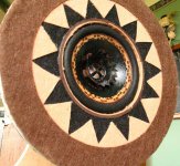
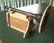
Here is a pic of the driver on the mounting block, but only taped on for photographic purposes, in the actual set-up they mount via steel saddles. The whole idea is to totally isolate the driver from the cabinet/baffle for a clean uncoloured sound.....which it does do very well indeed.
These drivers and LM1875 on batteries are a perfect match, the 6 watts or so is more than enough to drive them well.
These drivers and LM1875 on batteries are a perfect match, the 6 watts or so is more than enough to drive them well.
Attachments
Um, check the other input resistor. That's the load, Rin, and that one, ships 22k with your kit. Usual values are between 20k and 100k. Here is where there's a relationship with your input filter (Cin) cap, at the input load, Rin.
*Electrolytics at Cin may need to be larger--just go by speaker observation with tone generator.
*Add 330pF ceramic across Rin if you want an RF filter.
The suggested change to 10k will either cut the volume to half (Rb) or sponetaneously cause bass to disappear, depending on source (Rin).
Optional values to go with a 150k NFB, . . . is an Input of 120k vs 2.2k, plus an additional 100k load parallel with the input terminals (or whatever your passive pre has) --- or leaving it in the condition where it is sounding so good right now.
Document before altering!!
Input in-series (Rb) is 1k for K50 kit.
Those values correspond to basic "almost all the way" potentiometer scale values.
For input: 1k goes with 25k. 1.5k goes with 50k. 2.2k goes with 100k. 2.2k, 3.3k, 4.7k can all be used with the remaining values (100k to 220k).
That would be an "average optimals" scenerio, but not required.
Oh, and its National Semiconductor's spreadsheet. There's seems to be about 18% "padding" in the figures, so you can go a small amount, but not a huge amount, over the mark if the application calls for it.
You can use a signal generator, a recording of, or even an electronic piano/keyboard. If piano, a440 is an octave higher than a220, which is an octave higher than a110, and those figures are in Hz. A few post-it's later and you've got a signal generator. Quite a few post-its.
On speaker that does well at 60hz, check pitches 55hz compared with 65hz, compared with 75hz. The "just right" input filter cap size will have them at the same volume (SPL), and might even stretch that speaker down to 45hz (because it has less effort below that point).
Thanks SO much for discovering the speaker ground trace. I'll give that a try. Did you just reconnect the speaker ground to "0V"? Can you post a photo?
Zero One said:I am not sure why the larger voltage tranny sounds so much better, however the amp if run for full range applications does need a supply that doesn't sag under load, this is independent of the voltage, so my question is was the 18v one substantial enough for the job. There is not doubt that once the voltage sags the highs get muffled and the bass muddled.
Wow. WOW!! That's a beautiful speaker.
On the transformer? This is so weird! The champ power supply is a tiny little 36 va, 36vct (1 amp total 18+18VAC), Canadian made, with 4 diodes and 4 caps (4700uf per rail). The losers were. . . everything else, especially if larger.
I tried the larger supplies, 28vct 4A (muffled) and 36vct 4A (squeaky), with a simple supply, a smubberized supply, extra caps, bypass caps, and/or enough resistors to start looking like a christmas tree, and the el-cheapo mini supply still beat them on quality sound. ??????????
Okay, there was one larger goodie. A big 30 year old 55vct (28+28VAC) with the Brian GT power supply (using 4 MR860 diodes). Now that was cleaner. It was too hot. The dynamics were too fierce--Xmax all the time. One orchestra hit, and one had better have already been in the bathroom.
Its kind of like the old Memorex commercial--if one could add some temporarily airborne cats. Perhaps if I owned 16 ohm speakers? Well, you know my habit of heading, top speed, in whatever direction works, so I wound up with 36vct 1 amp monoblocks. They have sufficient headroom for dynamics at ear-botching volume levels. The problem (a nice one), is that it sounds so good that I'd like to turn it up more.
But, I do have to question why its working so well.
On 12v rails, have you tried B+P? I always loved the sound of bridged amps, but that would sound like 24v, so perhaps bridged + parallel?
This doesn't have to do with amplifiers, but I thought placing a speaker at the center of a circular baffle was the WORST case for diffraction loss - or does that not apply to OBs because the rear wave cancels out the front wave at the boundary? It's hard to see from your pictures but it appears that the rear of the speaker is inside some sort of enclosure. Is there a thread about these speakers in the full range or loudspeaker forums?
No, it's just a baffle. The larger the baffle the lower the frequency at which the response drops off. You can compensate for the baffle step by using a shelving filter. See here for example: http://www.trueaudio.com/st_diff1.htm
Hi BWRX
The speaker is mounted on a circle of ply, this is not the actual baffle, rather think of it as a mounting baffle which then goes inside a much larger baffle but without touching it, the real baffle is around 40 inches wide and and 36inches high but folded. the driver does not sit at the centre of this baffle at all, but is offset. The final baffles are under construction as we speak, in fact I am just about to sand the 2nd one for the gloss coats. Having the driver magnet mounted rather than baffle mounted makes for a whole different level of clarity, as the baffle is not coupled and therefore doesn't colour the sound. The little circular sub baffle does however add a nice bit of lower mid presence.
As an aside the design means I can swap out drivers for a different sound very quickly, any size up to 8 inches.
This really needs a whole separate thread but I am holding off till finished, in fact this is a complete system, here is a pic of most of the casework I am building before I sealed and sanded it.
In the end I will build a web page on the whole system but in the meantime a sneak peak.
Oh and my amps are built into the speaker cabs too.
Daniel I have not tried the bridged but I am definitely going to do this for the final system, it should give around 24watts.......plenty for big dynamics. I do expect it will sound the best of the lot but I have been tinkering a lot with trying to work out the perfect point to point layout and shielding arrangements. So soon.
Zero One said:Daniel I have not tried the bridged but I am definitely going to do this for the final system, it should give around 24watts.......plenty for big dynamics. I do expect it will sound the best of the lot but I have been tinkering a lot with trying to work out the perfect point to point layout and shielding arrangements. So soon.
I'd like to mention three things.
First, I just love the idea of a bridge LM1875, because this would let me voice it to "center stage" instead of the soundfield ahead of the driver. More power, more soundfield. Oh yeah!! Please share.
And, second, please don't be disappointed if bridged runs optimal at a different voltage. It will probably like 15vdc or 16vdc, but that's just a guess.
Maybe 3 smaller batteries per rail makes voltage options easier? To heatsink inside a speaker enclosure, I usually zoom through the cabinet with a doorknob bit (big round hole), and then Liquid Nail + screw the heatsink onto the cabinet (either side is fine). That's a siliconized construction adhesive, which is also a thermal compound, so the amp runs ice cold. I like to put it up with the drivers, so people think its a mystery speaker. LOL!
Oh yeah! I almost forgot to mention. For non-isolated LM1875, its good to shoot any exposed part of the heatsink (not where the chip goes) with clear lacquer to prevent shocks.
Daniel
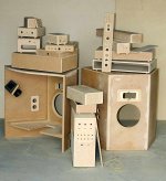
Here is a pic of the casework for 1 of the amps, this goes inside the speaker baffle. You will notice that there are 3 heatsinks, 2 for the bridged amp module and one for a purpose built tweeter amp, which will run different gain, input caps etc.
It will be painted gloss black to match the rear of the baffle.
Attachments

Zero One said:Daniel
Here is a pic of the casework for 1 of the amps, this goes inside the speaker baffle. You will notice that there are 3 heatsinks, 2 for the bridged amp module and one for a purpose built tweeter amp, which will run different gain, input caps etc.
It will be painted gloss black to match the rear of the baffle.
EDIT: Gloss black, with all that pretty woodwork, paint is almost a crime.
Ah, but what do the bicycle tires do? Is that a shop secret?
- Status
- This old topic is closed. If you want to reopen this topic, contact a moderator using the "Report Post" button.
- Home
- Amplifiers
- Chip Amps
- A Tale of Three LM1875 amps