Once in a while a new IC is released which lends itself to use with tubes.
This new one from Analog Devices is one, the AD8479 - it will measure differential voltages in the presence of up to +/-600 volts of common mode signal.
Want to monitor tube currents when neither side of the sense resistor is at 0V, this is the device to do it.
Ideal as the input device for any bias servo circuit. Will monitor cathode currents in any design I can think of.
Still not suitable for monitoring anode currents of output tubes (since the anode can swing to 2 x B+ due to the output tranny) but you can monitor screen currents (pentode mode) when the B+ is less than 600V and probably Ultralinear screen currents for B+ of less than say 400V.
Cheers,
Ian
I'm glad they finally completed the data sheet. The early one I haveat work did not include the common mode vs supply charts.
Note that you have to use +/-15V supplies to get to +/-600 input . Also the absolute max supply is +/-18V so you can actually run +/-16V and get a little more margin.
This is an upgrade over teh older AD629 (+/-250V).
Note that you have to use +/-15V supplies to get to +/-600 input . Also the absolute max supply is +/-18V so you can actually run +/-16V and get a little more margin.
This is an upgrade over teh older AD629 (+/-250V).
One thing to think about with this IC is that (like it's predecessor) it is thermally limited.
There is a spec for +/- 900V for 10 seconds. The IC uses a resistive input for current (and thus power) limiting.
So for normal operation, transients beyond +/-600V can be tolerated to a pretty reasonable extent. It is prudent to do some serious calculations for average power dissipation if you want to go over the +/- 600V limit.
If power limiting is a problem then you can still get the old INA117P (Burr Brown who are TI? these days) in an 8 pin dip, +/- 500V common mode ONLY though. I specified them for analog interfaces for an airborne survey system in 1993. Maybe a 15 or 20 scattered around the various electronics boxes. Never had a failure.
Cheers,
Ian
Cheers,
Ian
I was just pointing out that there are limits imposed on the device due to power dissipation and the major source si going to be due to the input resistor structure.
Given that the SOIC-8 package thermal resistance of 140 C/W or greater (depending on mfg, and not specified in the data sheet) and the input resistance is shown as 1MEG to each input, one can calculate the die temp.
For example if one is running a 500V supply:
Static dissipation is on the order of 2 X 500^2/1E6 = 0.5W
Thermal rise is thus 0.5 W * 140 C/W = 70 C minimum
So your amp is running in a nice cool 23C environment and internally you see 40C around the PCB. Now the die temp is up to 110C.
You decide to put on some Metalica and crank it up as you are in the kitchen cooking and you now add an additional 100Vrms to the static supply.
Now Pd is 2 * 600^2/1E6 = 0.72W
and thermal rise is up to 100.8C
Lets say your internal temp is now up to 50C since you are dissipating more power.
Now your die temp is up to 150.8C!
This exceeds manufacturer specification for die temp.
This isn't extreme, however a heat sink would be a good idea.
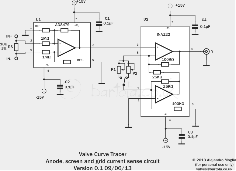
INA122
http://www.ti.com/lit/ds/symlink/ina122.pdf
I'm using this for cathode current monitoring.....you can attach a pot to dial in the output gain and it works from a single supply
TheGimp
If you are using it on the anode voltage just elevate the monitoring circuit to the anode voltage
http://www.ti.com/lit/ds/symlink/ina122.pdf
I'm using this for cathode current monitoring.....you can attach a pot to dial in the output gain and it works from a single supply
TheGimp
If you are using it on the anode voltage just elevate the monitoring circuit to the anode voltage
I like the analysis and conclusion by The Gimp
As a very experienced engineer in making things work at stupidly high temperatures for down hole equipment (oil and gas well drilling), I can tell you that typically, and very surprisingly, analog chips, especially those designed for the automotive industry, do very well at even 200C ambient temperatures. Once a thermal shutdown is introduced, then you are at its mercy. The typical shutdown has a lot of hysteresis and trips at about 160C then must be cooled to 140C before it will reset. In the case of this specific IC, the analysis is that AD's concern is over the resistor(s) which may be burning up if not monitored. So, the conclusion of keeping the IC as cooled as possible is very valid. Works for us in the down hole arena, together with keeping the dissipation as low as one can make it. Have not gone over the IC's specs but I wonder if, even at the cost of some degradation in performance, one could also add external resistance to reduce the internal dissipation.
For much more modest requirements, Linear Tech has several OP Amps which can have their inputs pulled to at least 40V while the supply is more the typical 12V SE, can't remember the number series but seems like LT1640 or some such.
BTW, AD is one of the companies whose products work downhole more often than not.
Rene
Now your die temp is up to 150.8C!
This exceeds manufacturer specification for die temp.
This isn't extreme, however a heat sink would be a good idea.
As a very experienced engineer in making things work at stupidly high temperatures for down hole equipment (oil and gas well drilling), I can tell you that typically, and very surprisingly, analog chips, especially those designed for the automotive industry, do very well at even 200C ambient temperatures. Once a thermal shutdown is introduced, then you are at its mercy. The typical shutdown has a lot of hysteresis and trips at about 160C then must be cooled to 140C before it will reset. In the case of this specific IC, the analysis is that AD's concern is over the resistor(s) which may be burning up if not monitored. So, the conclusion of keeping the IC as cooled as possible is very valid. Works for us in the down hole arena, together with keeping the dissipation as low as one can make it. Have not gone over the IC's specs but I wonder if, even at the cost of some degradation in performance, one could also add external resistance to reduce the internal dissipation.
For much more modest requirements, Linear Tech has several OP Amps which can have their inputs pulled to at least 40V while the supply is more the typical 12V SE, can't remember the number series but seems like LT1640 or some such.
BTW, AD is one of the companies whose products work downhole more often than not.
Rene
- Status
- This old topic is closed. If you want to reopen this topic, contact a moderator using the "Report Post" button.
- Home
- Amplifiers
- Tubes / Valves
- A new IC for monitoring tubes