I have described a relatively simple and undemanding HV regulator here:
https://www.diyaudio.com/forums/pow...ers-resistors-450v-reference-post5962982.html , but it requires a LT1013 as a gain engine.
Although it is a relatively cheap and common opamp; it doesn't qualify as a commodity: in some parts of the world, it could already be a kind of luxury.
Unfortunately, the circuit cannot tolerate a LM358 AND remain universal: the output stage of the 358 is too problematic for that.
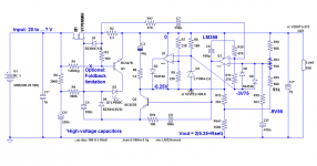
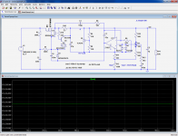
Here is an adapted version, especially tailored for the 358.
It requires an additional buffer transistor and a different compensation scheme, and the static regulation performances are somewhat less shiny, because the gain and accuracy of the LM358 are not as good as the LT1013's, but it remains a capable regulator.
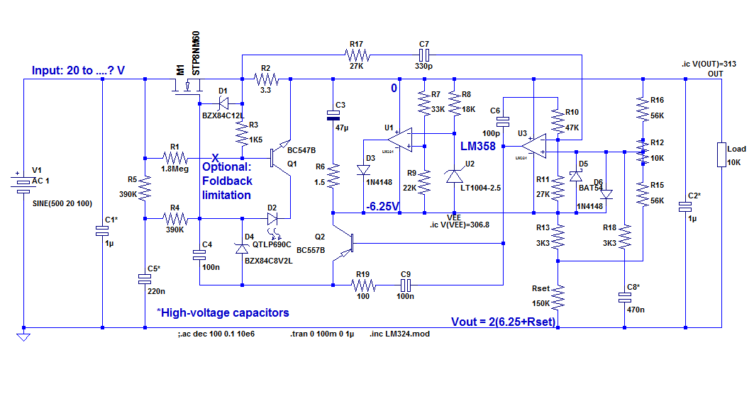
As in the previous circuit, the output voltage can be set with a single resistor.
The reference circuit also uses the AutoShunt principle, meaning many different types of references can be used: IC, LED, homebrew bandgap or even thermistors if you fancy it.
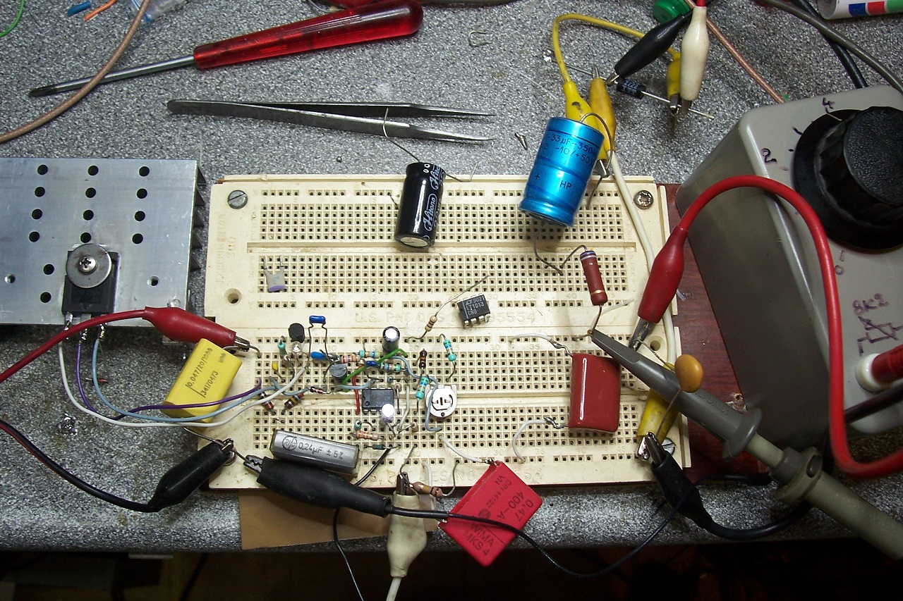
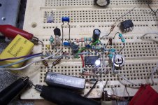
In my prototype, I have used a white LED, because it has ~the same voltage as the 2.5V shunt reference, and shows its operation in a visible way, which is useful for debugging work.
Although tailor-made for a 358, the circuit will also accept a LT1013, and many other dual opamps including GND in their CM range, but if you use a LT1013, it makes no sense to use this version, as it is more complicated and brings no benefit.
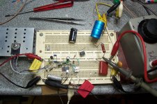
Here is the prototype in operation:

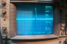
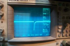
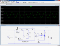
And here are the transient responses (with a static load of 12K and an output voltage of 215V).
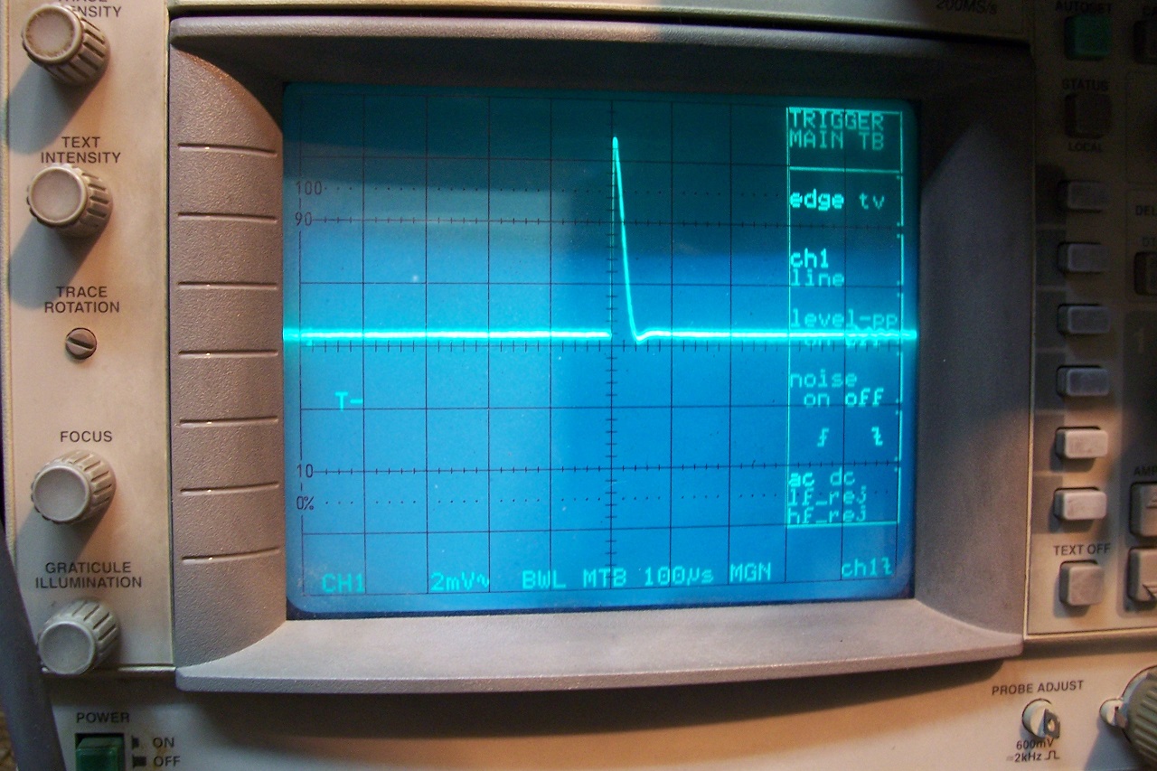

The negative transient response is cleaner than the positive one, which is logical for a 1-quadrant regulator.
As its predecessor, it is unconditionally stable, and suffers the same drawbacks of minimum output voltage and 5V dropout.
For a system supply, this shouldn't be a problem, but if you want to build a lab supply, a scheme like Elektria is preferable.
Note that if you do not like ICs, I have also described simplistic, fully discrete regulators, but more than one resistor value needs to be changed if you want to significantly alter the output voltage:
https://www.diyaudio.com/forums/power-supplies/198986-simple-hv-series-regulators.html
https://www.diyaudio.com/forums/pow...ers-resistors-450v-reference-post5962982.html , but it requires a LT1013 as a gain engine.
Although it is a relatively cheap and common opamp; it doesn't qualify as a commodity: in some parts of the world, it could already be a kind of luxury.
Unfortunately, the circuit cannot tolerate a LM358 AND remain universal: the output stage of the 358 is too problematic for that.
Here is an adapted version, especially tailored for the 358.
It requires an additional buffer transistor and a different compensation scheme, and the static regulation performances are somewhat less shiny, because the gain and accuracy of the LM358 are not as good as the LT1013's, but it remains a capable regulator.
As in the previous circuit, the output voltage can be set with a single resistor.
The reference circuit also uses the AutoShunt principle, meaning many different types of references can be used: IC, LED, homebrew bandgap or even thermistors if you fancy it.
In my prototype, I have used a white LED, because it has ~the same voltage as the 2.5V shunt reference, and shows its operation in a visible way, which is useful for debugging work.
Although tailor-made for a 358, the circuit will also accept a LT1013, and many other dual opamps including GND in their CM range, but if you use a LT1013, it makes no sense to use this version, as it is more complicated and brings no benefit.
Here is the prototype in operation:
And here are the transient responses (with a static load of 12K and an output voltage of 215V).
The negative transient response is cleaner than the positive one, which is logical for a 1-quadrant regulator.
As its predecessor, it is unconditionally stable, and suffers the same drawbacks of minimum output voltage and 5V dropout.
For a system supply, this shouldn't be a problem, but if you want to build a lab supply, a scheme like Elektria is preferable.
Note that if you do not like ICs, I have also described simplistic, fully discrete regulators, but more than one resistor value needs to be changed if you want to significantly alter the output voltage:
https://www.diyaudio.com/forums/power-supplies/198986-simple-hv-series-regulators.html
Attachments
Yes, it is a functional possibility, but I didn't retain it despite the common-mode advantage: the main problem are the transients transmitted by C8/R18: clamping them to a relatively delicate reference IC is not a viable option, meaning a schottky to the local -6.25V would still be necessary, plus probably a clamp diode to the local 0V (output).
In principle, in a securely connected system, such transients should not be present, but as we know (you seem to have a good expertise in this field), these things happen with HV circuits, and it is preferable to eliminate all possible weaknesses before they have the opportunity to bite you.
Another (accessory) reason for rejecting it was that the initial reference, as a source for the autoshunt principle, could have any voltage and be much less stiff than an integrated reference (thermistor, etc).
If the autoshunt is designed for a final voltage of 6.25V, the circuit is normalized and the formula remains valid without needing to alter other resistor values.
Having a second opinion like yours is always welcome anyway, and DIYers could decide to opt for it if they think it is fit for their purpose.
Like all my projects, this one is completely open, and everyone is free to add his/her contributionS

Well, perhaps a battery is not a very reliably reference.
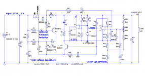
And i goofed up with the voltage and consequent resistor in the schematic i posted .
.
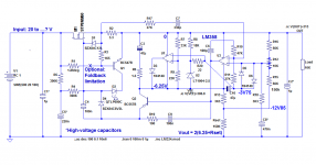
The voltage drop on R13 isn't 3V3 but 6V6 (2mA !) and R15 has to be 150k.
And maybe the transient clamping problem can be solved with a capacitor over U2.
Mona
And i goofed up with the voltage and consequent resistor in the schematic i posted
.The voltage drop on R13 isn't 3V3 but 6V6 (2mA !) and R15 has to be 150k.
And maybe the transient clamping problem can be solved with a capacitor over U2.
Mona
Attachments
What do you reckon, would some Class A biasing for U3 be of use? Q2 base current can't be that much, now can it? Added a 330k pull-down to GND, it didn't seem detrimental at least... ~1 mA seems like a more sensible output stage quiescent current than the 50 µA it's running stock.
Also, how about a cap across R7 to reduce reference noise, and a bigger cap in parallel to C8 for some more noise reduction? Both seem to have the desired effect. Probably of more use with a zener reference; an LED, by contrast, seems to appreciate an extra RC filter capacitor for its supply for reduced ripple (in return it sure looks much quieter in sim).
Also, how about a cap across R7 to reduce reference noise, and a bigger cap in parallel to C8 for some more noise reduction? Both seem to have the desired effect. Probably of more use with a zener reference; an LED, by contrast, seems to appreciate an extra RC filter capacitor for its supply for reduced ripple (in return it sure looks much quieter in sim).
It could be quite reliable: an alkaline cell has a voltage of 1.59V, practically zero-tempco, zero-noise and is durable provided no current is drawn.Well, perhaps a battery is not a very reliably reference.
What stops me is the need to properly handle the off condition: how do you prevent the battery from discharging into various parasitic junctions when the circuit is not energized.
This issue can be addressed of course, as it was in CMOS memories, but it means additional complication.
Yes, this is a viable and workable proposition, and in the original circuit C3 did the job of bypassing the transients away from the ICAnd maybe the transient clamping problem can be solved with a capacitor over U2.
Probably: the problem is caused by the class A to class B transition, so if U3 always remains in class A, it should be eliminated.What do you reckon, would some Class A biasing for U3 be of use?
The small signal BW of the LT1013 is similar to the LM358, and the LT1013 works directly, without additional buffer.
Q2's base current is tiny and isn't a problem.Q2 base current can't be that much, now can it? Added a 330k pull-down to GND, it didn't seem detrimental at least... ~1 mA seems like a more sensible output stage quiescent current than the 50 µA it's running stock.
To bias U3 in class A would require additional current, and since the regulator is fully floating and fed by the voltage-setting resistor, any additional consumption would need to pass through the Rset.
I opted for 2mA, and it already was a difficult tradeoff because the power at 500V output exceeds 1W.
Remember that the current through R4, R5 and possibly R1 also has to be sunk through Rset, and that the regulator is meant to be universal, even for insane input or output voltages within the 20V to ∞ input and 12.5V to ∞ output
Yes, I mentionned this possibility in the AutoShunt Thread, but the gain will be modest, a bit more than 6dB with a 2.5V reference.Also, how about a cap across R7 to reduce reference noise,
If the reference has a lower voltage, the gain would be more significant.
A larger C8 would benefit the VLF noise, not the 100Hz ripple nor the audio noise.and a bigger cap in parallel to C8 for some more noise reduction?
I opted for 470nF because it does not imply an E-cap, but if VLF noise or output impedance is particularly important, it could be increased (with a LM358, I estimate the 100Hz PSSR to ~120dB. with a LT1013 it is ~140dB)
Zeners, LEDs, or any forward-biased diode could benefit from an additional bypass cap. Integrated references like the LT1004 generally do not like a direct bypass for stability reasons, but with 100Ω series, any cap would be tolerable and the DC performances would remain unaffected, so there is room for improvement if needed.Both seem to have the desired effect. Probably of more use with a zener reference; an LED, by contrast, seems to appreciate an extra RC filter capacitor for its supply for reduced ripple (in return it sure looks much quieter in sim).
This circuit is broadly the discrete equivalent of a 3-pin VR, and similar improvement tricks can be used, except you can also act on internal nodes, normally not accessible in an integrated regulator.
Contributions like yours are welcome since they show the way to turn this GP regulator into a HV super-reg
Am I wrong or this is basically a Jung/Didden super regulator adapted for high voltages?
No chance! With so many parts you can probably build three J/D super-regs ;-)
If you want a J/D for higher voltages, this would work.
Jan

No, certainly not: the PSRR might qualify it for a super-reg, but the output impedance is several hundreds of milliohms, and with a 358, the noise performance is going to be average at best.Am I wrong or this is basically a Jung/Didden super regulator adapted for high voltages?
It is a Funk1980/LV regulator, optimized for component availability, low cost and tolerance to the outside world.....
Indeed, and at the cost of one J/D super-reg, you can probably build three (or more) of this oneNo chance! With so many parts you can probably build three J/D super-regs ;-)
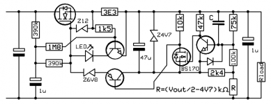
Yes, it is a nice and faithful translation in discrete components of this regulator.Just for fun, a simplex version, no opamps
Mona
I will probably give it a try in sim one of these days.
Need to? Why?To bias U3 in class A would require additional current, and since the regulator is fully floating and fed by the voltage-setting resistor, any additional consumption would need to pass through the Rset.
Ah, I see what you're getting at. My little pull-down resistor is obviously not universal - if that's required, it would have to be replaced by a full-fledged current source.Remember that the current through R4, R5 and possibly R1 also has to be sunk through Rset, and that the regulator is meant to be universal, even for insane input or output voltages within the 20V to ∞ input and 12.5V to ∞ output
With a less-than-ideally quiet reference, even 8 dB is quite welcome if it means 80 µV rather than 200 µV.Yes, I mentionned this possibility in the AutoShunt Thread, but the gain will be modest, a bit more than 6dB with a 2.5V reference.
Besides, startup seems to take the better part of 10 seconds as-is.A larger C8 would benefit the VLF noise, not the 100Hz ripple nor the audio noise.
And that's not bad for a bunch of jellybean parts.I opted for 470nF because it does not imply an E-cap, but if VLF noise or output impedance is particularly important, it could be increased (with a LM358, I estimate the 100Hz PSSR to ~120dB. with a LT1013 it is ~140dB)
That said, it still is mighty complex for my tastes. At least I'm slowly beginning to understand how the voltage setting business works - U3 compares (Vout-6.25V) to the midpoint between Vout and the lower end of R13, so that I(R13) = 6.25 V / R13, and then I(Rset) = I(R13) + 2*6.25V/(R12+R15+R16). It's ~= 2.017... mA in sim, as you said (BTW: a value of 2.008 mA is obtained with R15/16 = 62k).
In all its glory, the full formula for output voltage then becomes:
Vout ~= 2 * 6.25 V + 2.0 mA * Rset.
which simplifies to
Vout ~= 2 * (6.25 V + Rset/kOhm * 1 V)
Vout = 2(6.25+Rset) was making me feel really uneasy, I can tell you that much! (Dimensions! That would never have passed in physics lab.)
Attachments
It does not actually need to in fact: it is more a self-imposed constraint than an actual necessity.Need to? Why?
If the total current drain of the floating regulator + various other currents, like the foldback bias exceeds what Rset can sink, the voltage regulation will be lost under open-load conditions, and the output voltage will creep up, eventually towards the raw input voltage.
You could rightly say that even a small tube preamp is always going to draw enough current to prevent this situation from happening, thus for a system power supply, the open-output case can be dismissed (as opposed to a bench supply, which needs to behave in all circumstances, including no-load), but that would be ignoring some realities: tube gear needs some time before the heater allows cathode current to pass, and a standby switch interrupting the HV supply is not infrequent.
If you use such a supply to derive, say a 200V supply for a preamp from the main 600V of the output stage, the preamp supply could reach twice its nominal 200V until the tubes heat up properly.
This could have consequences for some components, like capacitors.
I think you saw the reason:
Note that the regulation properties under no-load conditions are going to be pretty poor: not only is the gm of the MOSfet low, but the output configuration is highly asymetrical (~1 quadrant), requiring a peculiar compensation and a blunting of normal-load regulation performances, but I think it is price worth paying.Ah, I see what you're getting at. My little pull-down resistor is obviously not universal - if that's required, it would have to be replaced by a full-fledged current source.
I completely agree: if you are after an optimum noise perf, even the odd dB shouldn't be scorned atWith a less-than-ideally quiet reference, even 8 dB is quite welcome if it means 80 µV rather than 200 µV.
Yes, could act as a soft-startBesides, startup seems to take the better part of 10 seconds as-is.
The (relative: look at the breadboard implementation) complexity results from an evolution starting several years ago, when Funk1980 asked me to have a look at a HV regulator.That said, it still is mighty complex for my tastes.
I proposed a first circuit, and it was implemented with a LM358, because of cheapness and universality.
Only half of the package was needed (there is a single version of the 324/358, but it is confidential and probably costlier than a 358), and I found a use for the second operator as a shunt regulator.
I then had the idea of converting this working, single-purpose design into a more universal one, but it required an additional transistor and a more elaborate compensation scheme.
That's where it ended now, but you can rewind, and undo most of the mods whilst retaining the universality: use a single opamp, even one that does not include GND in its CM range thanks to Mona's mod, ditch the AutoShunt and use a Lo-Po TL431-like reference (the regular TL431 requires more current than the LT1004 + 1/2 LM358).
If the opamp is half-decent, it will not need an additional buffer, meaning further simplifications.
The present circuit has the advantage of being completely universal (it can use almost anything vaguely non-linear component as a reference), completely commoditized (the LM358 is available everywhere), and has remarkable performances thanks to the complete stasis allowed by the autoshunt, but if you opt for more conventional solutions, there can be significant simplifications
Well, it's like all easy-to-use formula's: for example the 1/Gm one for semi junctions: 26/Ie gives the value in ohm with Ie in mA.Vout = 2(6.25+Rset) was making me feel really uneasy, I can tell you that much! (Dimensions! That would never have passed in physics lab.)
We know that this is not proper and homogeneous, but it is easy and convenient, and as long as we know what it actually stands for, it is a convenient mental shortcut.
Life is too short too worry about such details.... if you know what you are doing
Another nice one to make you really cringe: do you know that the VA rating of an ordinary, silicon steel transformer can be estimated with this formula: P(VA) = A², A being the core area expressed in cm² (for a 50Hz system).was making me feel really uneasy, I can tell you that much! (Dimensions! That would never have passed in physics lab.)
This would mean that 1VA (having the dimension of W) = 1cm4 (1e-8m).
Of course, there is a hidden constant in the formula, having complicated dimensions which happens to be exactly 1 for the very peculiar conditions and units specified.
If you try to draw general conclusions from this example, without really understanding all the implications, you will be going straight and and fast into a wall
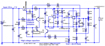
Here is how would such a reg look like (only an example, has not been tested in reality or refined in any way).That's where it ended now, but you can rewind, and undo most of the mods whilst retaining the universality: use a single opamp, even one that does not include GND in its CM range thanks to Mona's mod, ditch the AutoShunt and use a Lo-Po TL431-like reference (the regular TL431 requires more current than the LT1004 + 1/2 LM358).
If the opamp is half-decent, it will not need an additional buffer, meaning further simplifications.
I used a standard TL431 and it works, because of the low consumption of the LT1637 (a randomly selected opamp) and the built-in margins, but that's not something I recommend: use a low-power version like the TLV431.
It should decrease the no-load consumption to under 1mA, allowing you to increase Rset to the point of being a 1/2 or 1/4W type (having a sufficient voltage rating though)
Using asymetric bridge resistors, in Ketje/Mona's fashion would allow you to use an opamp not having GND in its input CM range.
The complexity is significantly decreased, yet there are still optional bells and whistles, like the current-limiter with its indication LED, and the filter cell R2 C2
Attachments
An important note about the components selection:
The MOSFET must include the coordinates (Vin_raw, Iout_max) inside its DC safe operating area, even if the foldback option is implemented.
The foldback feature can be used to reduce thermal requirements, but not the fundamental V x I capability.
The zener (D4) needs to have voltage allowing the opamp's output to sit at 3V above the local -6.25V under median conditions.
Since the G-S voltage under those conditions is going to be close to Vto, this would be 3.25v + 0.3V + Vto, but at relatively low current: a few hundreds of µA's.
The Vto depends on the exact MOS type used: in general, legacy types are around 4V, and more recent devices have 3V, sometimes less.
If the zener voltage is too high, the circuit will lose the regulation at low currents, and if it is too low, it will run out of steam at higher currents.
- Status
- This old topic is closed. If you want to reopen this topic, contact a moderator using the "Report Post" button.
- Home
- Amplifiers
- Power Supplies
- A commodity-based HV regulator: FlexHV