Hi fellas,
I decided to start a thread about my project to do some parts replacement on this amp. I am looking for insights and suggestions from you, and maybe help others with similar project in mind. I'd like to start by saying a big heap of thanks to Bob (trileru) for walking me thru the entire process up until now. You rock big time.
Schematic and service manual:
Dropbox - Sony TA-1055
I re-upload some photos via flickr for your reference.
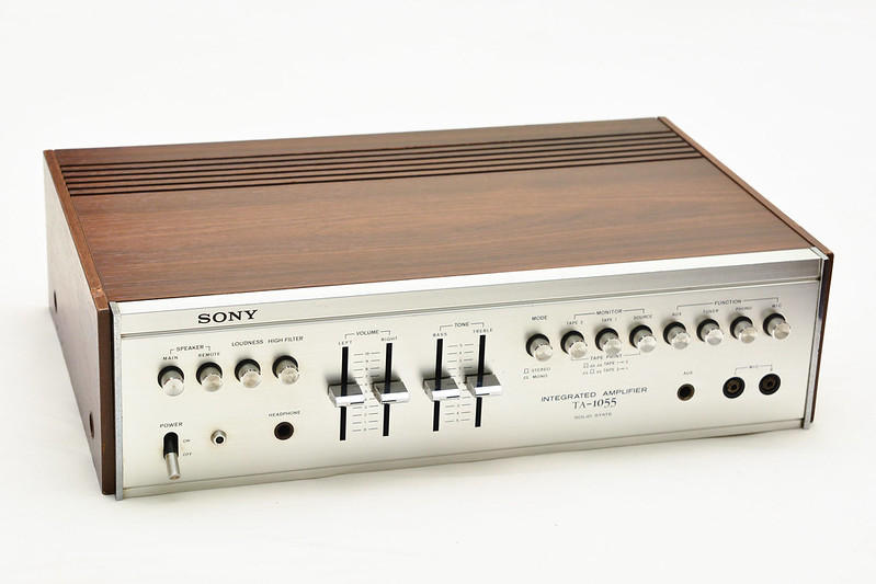
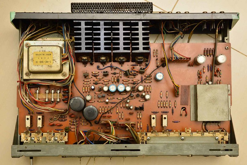
So here's the amp:
The board:
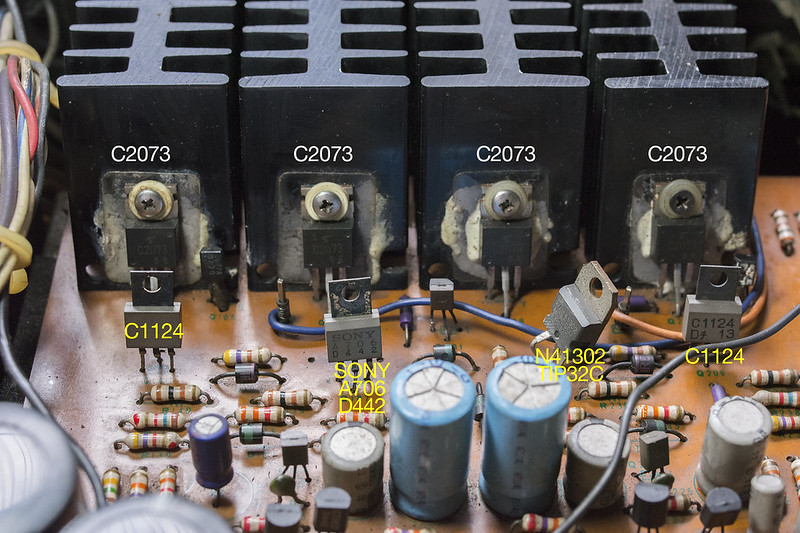
Little did I know the final transistors were replaced, and one of the drivers are not original:
So I started compiling a parts list, anything under 10uF has been replaced with film caps, and most of the caps are replaced.

Bringing the whole thing to look like this:
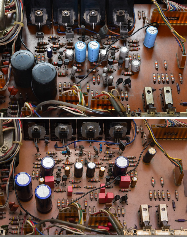
Not too shabby, eh?
HOWEVER, DC offset is high on one channel and now the amp keeps blowing fuse. The story continues on page 6.
I decided to start a thread about my project to do some parts replacement on this amp. I am looking for insights and suggestions from you, and maybe help others with similar project in mind. I'd like to start by saying a big heap of thanks to Bob (trileru) for walking me thru the entire process up until now. You rock big time.
Schematic and service manual:
Dropbox - Sony TA-1055
I re-upload some photos via flickr for your reference.
So here's the amp:
The board:
Little did I know the final transistors were replaced, and one of the drivers are not original:
So I started compiling a parts list, anything under 10uF has been replaced with film caps, and most of the caps are replaced.
Bringing the whole thing to look like this:
Not too shabby, eh?
HOWEVER, DC offset is high on one channel and now the amp keeps blowing fuse. The story continues on page 6.
Last edited:


So you are replacing all the transistors as well ? It should certainly be do-able but you may run into issues of both stability and also basic issues such as being able to obtain the correct bias current in the output pair. It looks like this is a fixed bias design and so its especially critical of the parts used. This is because of manufacturing differences between old vs new semis and the slightly different characteristics in things such as absolute turn on voltage.
Restoring old gear is great... if you dismantle it further then its even possible to wash the main PCB and chassis etc. Hot water and detergent. It would all come up like new.
Restoring old gear is great... if you dismantle it further then its even possible to wash the main PCB and chassis etc. Hot water and detergent. It would all come up like new.
Mooly, I'm replacing 4 driver transistors and 4 output transistors, simply because the ones installed are not correct for this amp. There are smaller ones that I think I'll just leave as is. I'm replacing the caps as well, putting film caps in place of 'lytics, and also some diodes as well to be safe.
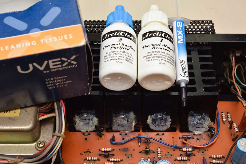
I'll see about removing the board altogether. Right now I'm fairly content with cotton swab and alcohol, working slowly around each part I'm replacing. Thanks for stopping by.
I'll see about removing the board altogether. Right now I'm fairly content with cotton swab and alcohol, working slowly around each part I'm replacing. Thanks for stopping by.
Thanks Mooly.
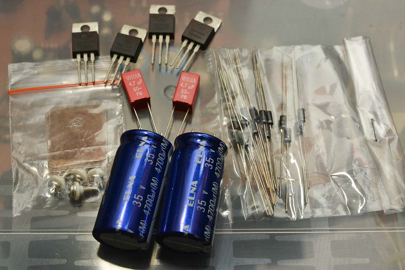
The parts started to arrive, yay. A few things, the legs of the big caps were spaced at 7mm and the board is designed for 13mm. A few twist and turns with the plier and we're good. And the TO220 insulation kit I bought uses 3mm screw and the heatsink accepts something like 2.5mm? So that means a trip to the hardware store tomorrow.


The parts started to arrive, yay. A few things, the legs of the big caps were spaced at 7mm and the board is designed for 13mm. A few twist and turns with the plier and we're good. And the TO220 insulation kit I bought uses 3mm screw and the heatsink accepts something like 2.5mm? So that means a trip to the hardware store tomorrow.
Here's the bill of material, these are what I can find locally, with two Wimas coming from eBay.

@kct: Thanks for that, I tried pairing the power transistors as described here and found:
#1 .612
#2 .613
#3 .612
#4 .613
I'll let them sit together and re-test later in the afternoon, see if that changes anything.

@kct: Thanks for that, I tried pairing the power transistors as described here and found:
#1 .612
#2 .613
#3 .612
#4 .613
I'll let them sit together and re-test later in the afternoon, see if that changes anything.
Last edited:
Okay so I let them sit in an airconditioned room, tried not to touch them or expose them to heat source, measured once every one hour, and the result is:
#1 531
#2 530
#3 535
#4 532
How do you suggest I pair them? With the heatsink facing me, left to right is 1-2-3-4, does that necessarily means left and right channel, two transistors per channel?
#1 531
#2 530
#3 535
#4 532
How do you suggest I pair them? With the heatsink facing me, left to right is 1-2-3-4, does that necessarily means left and right channel, two transistors per channel?
Matching is stupid, don't even bother attempting it.
Gain matching power devices is generally good practice. With amplifiers it helps to improve performance, so conclusion: it is not stupid, it is smart.
Sure the amp will work ok without matching anything just not a good as it could work.

Its never easy working off pictures.
I would have thought that the collector of the originals would have been the centre pin... obviously check that, don't take my word for it.
Use your meter and check that the collector on the board (the print) goes to where you think it goes on the circuit.
I would have thought that the collector of the originals would have been the centre pin... obviously check that, don't take my word for it.
Use your meter and check that the collector on the board (the print) goes to where you think it goes on the circuit.
- Status
- This old topic is closed. If you want to reopen this topic, contact a moderator using the "Report Post" button.
- Home
- Amplifiers
- Solid State
- '74 Sony TA-1055 Recapping Project