Hi,
I have an appropriately-sized PT for a four valve Webcor amp I'd like to rebuild. The HT off the secondary does not have a CT so I was thinking of using the 6X5 GT with two diodes in a hybrid bridge.
I looked at valve wizard and I see they have the diagram with a current-limiting resistor along one leg of the HT/plate leads. Do I need this for this small of a load? The amp uses (2) 12A*7s and (2) 6V6 GT in push pull. Not a lot of current drawn. I believe the limit on the 6X5 is 70mA.
Can I stick with the two diodes?
If this is for musical instrument purposes, the thread should be move to Instruments and Amps.
Go directly to the 6X5 data sheet. Please observe that a certain amount of resistance is needed in series with both plates, when cap. I/P filtration is employed. As the value of the I/P cap. increases, that resistance becomes ever more important in preventing power on arcing. I suggest you use no more than 15 μF. in the I/P cap. position and follow it with a LC section. The reservoir capacitance can be comparatively large, courtesy of the choke's isolating action.
The vacuum rectifier's requirements and behavior dominate the PSU, totally. 2X UF4007s forming the hybrid bridge's connection to ground will be quite satisfactory.
Thanks for the reply Eli. The amp is for an old Webcor turntable that only really turna 45s. It is for friend and not intended for instruments.
The original smoothing network in the amp is 32+32+15 with 2.2K between the 32ufs and 68K across 32uf-15uf. I suppose I could try to redo the power supply in PSUD2. The chassis is pretty crowded, not sure where I'd stick the choke.
The original smoothing network in the amp is 32+32+15 with 2.2K between the 32ufs and 68K across 32uf-15uf. I suppose I could try to redo the power supply in PSUD2. The chassis is pretty crowded, not sure where I'd stick the choke.
OK, space is at a premium. So, CRC style filtration will have to do. How is the OEM 32/32/15 packaged and distributed? What's the approx. B+ rail voltage?
Modern 'lytics are much more volumetrically efficient than the old stuff. The I/P cap. can be held to 15 μF., for vacuum rectifier "comfort", the 1st between caps. resistor's value tweaked (via PSUD2), and the reservoir capacitance increased to 100 μF. Tweaking the small signal RC decoupling network rates to be warranted too. Increase the value of the cap. from 15 μF. to 22 μF.
Please upload the OEM schematic, if you have it. I "smell" a record damaging piezoelectric cartridge. However, we're talking 45s, not irreplaceable LPs.
Modern 'lytics are much more volumetrically efficient than the old stuff. The I/P cap. can be held to 15 μF., for vacuum rectifier "comfort", the 1st between caps. resistor's value tweaked (via PSUD2), and the reservoir capacitance increased to 100 μF. Tweaking the small signal RC decoupling network rates to be warranted too. Increase the value of the cap. from 15 μF. to 22 μF.
Please upload the OEM schematic, if you have it. I "smell" a record damaging piezoelectric cartridge.
However, we're talking 45s, not irreplaceable LPs.I just realised after reading more on the internet that the hybrid bridge might not be the answer. I was wondering how it was working before without the diodes on the legs.
Apparently some of the old Webcore transformers had their CTs internally grounded as a cost-cutting measure. This player is the Model 1133, from 1955. It never crossed my mind that this could be the case! I should have measured to the frame before reinstalling the PT!
I will desolder the leads and measure to the frame. This must be the explanation.
It still doesn't explain the filter network, however. I've incuded the schematic with the plate voltages, but the values of the filter network are different and what I listed in the previous post.
Attachments
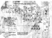
By George, I see a mag. cart., which is a pleasant surprise.
The 70 mA. 6X5 is at its very limit, perhaps overworked, feeding that signal setup. We can pick up 150 mA. or so of extra heater current, by replacing the #47 pilot lamp with a LED, PN diode, and current limiting resistor series combo wired across the power trafo's primary. That 150 mA. extra will go a long way towards energizing a more capable rectifier's heater, without inducing excessive filament winding stress. Remove the 6X5's Octal socket and install a Loctal socket in the opening. Use the 100 mA. capable 7Z4 to rectify the B+.
Talk about inconsistency. Cheapness around the power trafo combined with a mag. cartridge. Perhaps the power trafo frame should be electrically isolated from the chassis with nylon hardware, the connection you previously mentioned made via a solder lug and local connection to the chassis made via a cap. and another solder lug. Getting signal out of the chassis should lower the unit's residual hum level.
BTW, the "death cap." must go and a proper 3 wire, safety grounded, power cord installed.
The 70 mA. 6X5 is at its very limit, perhaps overworked, feeding that signal setup. We can pick up 150 mA. or so of extra heater current, by replacing the #47 pilot lamp with a LED, PN diode, and current limiting resistor series combo wired across the power trafo's primary. That 150 mA. extra will go a long way towards energizing a more capable rectifier's heater, without inducing excessive filament winding stress. Remove the 6X5's Octal socket and install a Loctal socket in the opening. Use the 100 mA. capable 7Z4 to rectify the B+.
Talk about inconsistency. Cheapness around the power trafo combined with a mag. cartridge.
Perhaps the power trafo frame should be electrically isolated from the chassis with nylon hardware, the connection you previously mentioned made via a solder lug and local connection to the chassis made via a cap. and another solder lug. Getting signal out of the chassis should lower the unit's residual hum level.BTW, the "death cap." must go and a proper 3 wire, safety grounded, power cord installed.
I'll have to take a look at the cartridge again. I remember it being a silver GE-labeled, but that's about it. The turntable looks pretty cheap, but I imagine the circuit might not be the best either? (Something mentioned elsewhere about converting these over to cheap practice guitar amps). Needless to say, I think the guy wants to just give this thing a go due to its age. I'll propose the 7Z4 and loctal socket idea and see if he goes for the extra "investment."
I am still waiting on the filter caps in the post, so I was just cleaning, redressing the amp and testing the PT. The nylon washer idea is spo on. I'll have to run to the hardware store tomorrow and grab them.
I am still waiting on the filter caps in the post, so I was just cleaning, redressing the amp and testing the PT. The nylon washer idea is spo on. I'll have to run to the hardware store tomorrow and grab them.
The phono preamp is, most definitely, GE style. It combines 10 Kohm R1 with the cart.'s inductance, as part of the EQ process. Also, 4.7 Mohm R2 provides quite a bit of grid leak, AKA contact, bias.
The cart. is 1 of GE's famous variable reluctance models. It's moving iron in nature and, for the most part, behaves along the lines a modern MM cart. does. It takes a substantial tracking force, about the same as piezoelectric carts. take, but it will not scrub HF info. out of record grooves.
The cart. is 1 of GE's famous variable reluctance models. It's moving iron in nature and, for the most part, behaves along the lines a modern MM cart. does. It takes a substantial tracking force, about the same as piezoelectric carts. take, but it will not scrub HF info. out of record grooves.
I spoke with the owner and as it will only play mono and it only cost them fifteen bucks, they so not wish to pursue it.
Having already invested a few hours in it, I'm curious to see how it sounds. I'm not sure I want to invest in the 7Z4 and that pricey loctal socket.
Perhaps I should just replace the valve rectifier with a full diode bridge?
There is also another input in the back that appears to bypass the turntable input.
Last edited:
The PSU has to stay FWCT, but we can switch to 2X series wired pairs of UF4007s as the replacement for the 6X5. Insert a CL-90 inrush current limiter between the rectifying SS diodes and the 1st filter capacitor. Damaging the power trafo with a turn on surge is not a good idea. Under $4 will buy the 4 diodes and thermistor.
Because of greatly reduced rectifier forward drop, the 1 W./2.2 Kohm resistor between the 1st and 2nd filter caps. needs to become both higher wattage and a higher resistance that's TBD. A cheapy metal oxide part is good enough in this slightly better (mag. cart.) than LOFI unit. Notice the absence of loop NFB and the fact that g2 B+ and O/P tube B+ come from the same point. Hardly a paragon of linearity and damping factor.
A clamp mounted 'lytic could go in the hole currently occupied by the 6X5 and its socket.
BTW, a Loctal socket is $2, from here. The same source wants (sic) $3 for a 7Z4. Seems inexpensive enough to me. Even better deals may be "lurking" on the WWW.
Thanks for all the help Eli. I had the suspicion that the amp might not be worthwhile. I see what you mean about the lack of NFB and the screen/plate voltage.
I also appreciate the link to the rectifier and socket. I haven't seen that website and those prices are very good. I will definately order a few of these irregardless. But for now there is no rush and I'll be putting it on the backburner.
I also appreciate the link to the rectifier and socket. I haven't seen that website and those prices are very good. I will definately order a few of these irregardless. But for now there is no rush and I'll be putting it on the backburner.
- Status
- This old topic is closed. If you want to reopen this topic, contact a moderator using the "Report Post" button.
- Home
- Amplifiers
- Power Supplies
- 6X5 GT Hybrid rectifier