Under "text book" conditions for a plate and screen voltage of 250V, and a grid bias of -12V the supposed plate current is approximately 42 mA with a screen current of around 3mA. This is more or less what you'd find right out of any RCA Radiotron data book.
Simulations in Spice produce the expected plate and screen current under the above stated conditions..
When I actually designed and finally built the amplifier, the current I actually get with -12V grid bias is about 1/3 of that predicted. No big deal except that my bias supplies are 12V camera batteries (A23), and therefore not readily adjustable. (9V batteries should in theory result in too much plate current, but I could reduce the screen voltage to compensate at the expense of lost open loop gain)
I've not designed much with the 6V6 - this is actually my first SE pentode amp design ever ( what's the world coming to ) and was somewhat surprised that the stated conditions are no where close to what I am measuring in the amplifier. The tubes are used Kenrad 6V6GT and are consistent channel to channel, and test good. I also have a pair of GE 6V6GT and will evaluate them next. This is not a small difference from the stated expectations for the given conditions but at least 300% off the mark. (I'd not have been surprised at 50% or so, but these aren't semiconductors...)
My thoughts are to drop the bias battery voltage with resistive divider which unfortunately does mean that they will have to be replaced from time to time. (I'll just replace the current grid resistor with the thevenin equivalent divider network that gives me the right voltage. Unfortunately this will kill the batteries rather quickly. A few months and they would have to be replaced. - I may use an opto isolator driven by the filament supply to ground one end of the bias string. Fail safe)
Interestingly reducing the bias to -11V at the grid had an insignificant effect - the plate current increased by less than 25%. I think I need to have another look at the characteristic curves as this is not adding up.. (large change in the slope of the transconductance as the current goes up?)
The amplifier is a simple pentode with a 6J7 driver, and internal local feedback. (6V6 plate to 6J7 cathode - it's not too different than a classic design floating around on the web) The amp has fixed bias in the output stage and had screen regulation as well which is currently disabled.
It looks like I should have found the space for a conventional bias supply and a set of pots for bias adjustment. (I actually have an idea how I can derive the bias supply if needed from the existing plate supply and it would be self compensating..)
Transconductance must be all over the place with these types for them to not even come close to matching the data book operating point under nearly identical conditions.
I'm going to use a couple of regulated supplies and determine empirically just what conditions are required to get the stated plate current at 250V on the plate.
Anyone have any useful thoughts? George, Wavebourn?
Simulations in Spice produce the expected plate and screen current under the above stated conditions..
When I actually designed and finally built the amplifier, the current I actually get with -12V grid bias is about 1/3 of that predicted. No big deal except that my bias supplies are 12V camera batteries (A23), and therefore not readily adjustable. (9V batteries should in theory result in too much plate current, but I could reduce the screen voltage to compensate at the expense of lost open loop gain)
I've not designed much with the 6V6 - this is actually my first SE pentode amp design ever (
what's the world coming to ) and was somewhat surprised that the stated conditions are no where close to what I am measuring in the amplifier. The tubes are used Kenrad 6V6GT and are consistent channel to channel, and test good. I also have a pair of GE 6V6GT and will evaluate them next. This is not a small difference from the stated expectations for the given conditions but at least 300% off the mark. (I'd not have been surprised at 50% or so, but these aren't semiconductors...)My thoughts are to drop the bias battery voltage with resistive divider which unfortunately does mean that they will have to be replaced from time to time. (I'll just replace the current grid resistor with the thevenin equivalent divider network that gives me the right voltage. Unfortunately this will kill the batteries rather quickly. A few months and they would have to be replaced. - I may use an opto isolator driven by the filament supply to ground one end of the bias string. Fail safe)
Interestingly reducing the bias to -11V at the grid had an insignificant effect - the plate current increased by less than 25%. I think I need to have another look at the characteristic curves as this is not adding up.. (large change in the slope of the transconductance as the current goes up?)
The amplifier is a simple pentode with a 6J7 driver, and internal local feedback. (6V6 plate to 6J7 cathode - it's not too different than a classic design floating around on the web) The amp has fixed bias in the output stage and had screen regulation as well which is currently disabled.
It looks like I should have found the space for a conventional bias supply and a set of pots for bias adjustment. (I actually have an idea how I can derive the bias supply if needed from the existing plate supply and it would be self compensating..)
Transconductance must be all over the place with these types for them to not even come close to matching the data book operating point under nearly identical conditions.
I'm going to use a couple of regulated supplies and determine empirically just what conditions are required to get the stated plate current at 250V on the plate.
Anyone have any useful thoughts? George, Wavebourn?
Last edited:


Athos, I'll draw up a schematic once I have something that actually works and post it here.. In the mean time I'm hoping someone will weigh in w.r.t my original comments about the correlation between published specification and bench measurements of the 6V6 because frankly they don't seem to. (At least for this particular pair??)
After I finish lunch (just got back from the rink and our Sunday afternoon ice dance lesson) I will head downstairs, play some music and set up for some serious bench measurements.
Yves, very interesting design that incorporates some similar features although implementation is very different. In fact your bias source is exactly what I was planning to do as a last desperate act - with regulated screens I should be able to use battery derived fixed bias, without probably somewhat ill-advised. (I won't regulate the bias in that case)
Your numbers do seem to imply that there might be something odd about those Kenrad tubes I'm using - so I will swap them out. (Your stated operating point is very close to mine)
Last edited:
Glad you like it !
ECC812 looks very like an ECC85, something in between a 12AT7 and a 6BQ7.
Yves.
Hi Kevin, cross posting
I fear your tubes are not in mint condition . . .
I've built at least 3 samples of this amp with various 6V6, from old coke bottle to tubular shape with almost the same working point.
ECC812 looks very like an ECC85, something in between a 12AT7 and a 6BQ7.
Yves.
Hi Kevin, cross posting
I fear your tubes are not in mint condition . . .
I've built at least 3 samples of this amp with various 6V6, from old coke bottle to tubular shape with almost the same working point.
Last edited:
Kevin, it looks like the discrepancy between the text book condition for the grid bias and the actual results you got should be looked at. There may be something wrong with the tube(s) you use. Else, it doesn't make sense.
Yves, I'd use a separate winding, or separate trafo for the negative bias supply. A 12-15 Volt trafo with low current consumption isn't expansive.
I'd also prefer LC or CLC HT filter, rather than CRC.
Yves, I'd use a separate winding, or separate trafo for the negative bias supply. A 12-15 Volt trafo with low current consumption isn't expansive.
I'd also prefer LC or CLC HT filter, rather than CRC.
Anyone have any useful thoughts? George, Wavebourn?
No thoughts, but real measurements.
I took a Simple SE which is cathode biased. I ran it on an external power supply in triode mode. I set the power supply for 262 volts on the plate of the tubes and then tweaked the cathode resistors for 12 volts on the cathode. This leaves the desired 250 volts across the tubes. The cathode resistors wound up at 280 ohms (two 560's in parallel). That gives me 43 mA for plate and screen which is close to the data sheet values. I tried NOS GE, NOS wafer based Sylvania, NOS green lettered Sylvania, and my favorites the grey glass RCA's. All were within 0.5 volts of 12 V.
I usually run 6V6's a bit hotter, OK quite a bit hotter, but this seems to sound pretty good. I think it sounded better when I used the little Edcor OPT's, but that was almost 2 years ago. I have Transcendars in there now. Both watts were straining to squeeze their sound out of my 88db Yamaha speakers, but I will revisit this combination when I get my horn speakers finished!
OH, yeah while I was at it I dropped in a pair of $1 tubes. The current went up to 57 mA (expected) and the sound got fatter with more bass. Maybe I will just turn the power supply up a bit.......
The local feedback arrangement you are using from 6V6 anode to 6J7 cathode MAY be responsible for the difference from book value you are seeing. With this feedback my quick trigger pull guess (haven't worked thru' the math) is that you are trading 6V6 gm for reduced rp - so of course the bias point will change. The feedback has reduced the gm to 1/3 so at book value bias you get 1/3 the idle current you expected. If your local feedback level is 10.5dB (a quick compare of open and closed loop gain will tell you what it is) then this is exactly what I would expect to see.
Cheers,
Ian
Cheers,
Ian
Thanks for all of the responses. I'm on new ground here, and making some significant mis-steps as you'll see below.
Turns out the bloody thing was finding more than a few ways to oscillate and that is why nothing made any sense. Anyway after fixing the myriad oscillation problems mostly in the 6J7 based driver stages I did in fact find out that my 12V batteries with a modicum of cathode bias (~0.5V) did in fact put me in the ball park.
Lots of problems overall with this pentode driven pentode output stage, but most have been worked out at this point.
Lesson learned: At first sign of trouble scope everything!
And because I was concerned about stability I loaded the secondaries of the OPTs prior to starting the bench work. Good thing I did, probably would have fried them otherwise.
I'm going to crank a little more current through the tubes to see whether or not I can achieve more than a couple of watts at acceptable distortion. This I will do mainly by switching to a more efficient rectifier tube. (Intended to use 5Y3, oddly sole example was bad - using 5U4GTB instead, probably will use a nice GZ32 I have on hand for some extra voltage.)
So what I have right now is a design with CRCLC filter with the output of the CRC section feeding the plates of the 6V6s, and the output of the LC feeding the 6V6 screens and plates/screens of the 6J7s.
I'm probably going to apply some overall feedback as well as I have a little gain to burn and need to drop the 120Hz buzz at the output by at least 6dB and I am reaching the point of diminishing returns on the psu side. (I could replace the 200 ohm resistor in the CRC with an L if I can find one that is physically reasonably sized and has a H or so of inductance at ~120mA or so..) The inductor is good for a couple of additional dB of buzz reduction on the output. Right now I measure 7mVrms which is far more than I am willing to tolerate. I'd be happy with <3mV although I generally target <1mVrms.
More when I next work on this.. It strikes me that this might not be a great design for anyone else to build although I will share it once I am sure it does not blow up.. (at least)
I think the main problem with this design is actually the pentode driver.
Sonically speaking I have no idea what to expect. Sine waves look fine..
Last edited:
I was away from my computer the whole day today, so did not see your first post, sorry. It is great you've found the cause of strange behaviour!
I can't find that archive of files for 6V6 that contained nice anode curves with variable G2 voltage, but I remember I was going to try it with something like 10-12K load, about 450V B+, and something between 150 and 200V on G2. It looked nice on the paper.
I can't find that archive of files for 6V6 that contained nice anode curves with variable G2 voltage, but I remember I was going to try it with something like 10-12K load, about 450V B+, and something between 150 and 200V on G2. It looked nice on the paper.
More when I next work on this.. It strikes me that this might not be a great design for anyone else to build although I will share it once I am sure it does not blow up.. (at least)
I think the main problem with this design is actually the pentode driver.
Sonically speaking I have no idea what to expect. Sine waves look fine..
The reason for my interest was that I was going to make the exact same circuit except with an 6SJ7 or EF86 driver. I'll be interested in your listening impressions. I was hoping it would end up a little more "Hifi" than "Guitar"
Athos
Athos
Why pentode? Because of Schade feedback? Getting 1% distortion at 5 watts without feedback is possible, someone did it tweaking the 12ax7 plate and cathode resistor values. 6V6 gives 5% so a lot of distortion cancellation was achieved.
Gnfb in a 6V6 SEP sounds good to me - better than the Schade loop in Alex Kitic design.
I would use a triode driver.
Gnfb in a 6V6 SEP sounds good to me - better than the Schade loop in Alex Kitic design.
I would use a triode driver.
The reason for my interest was that I was going to make the exact same circuit except with an 6SJ7 or EF86 driver. I'll be interested in your listening impressions. I was hoping it would end up a little more "Hifi" than "Guitar"
Athos
Athos
It's a stereo hi-fi amp, can't play the guitar to save my life.
From what I have measured so far with the exception of the excessive buzz on the output (which I will fix) the amplifier should perform decently at a couple of watts output. 20Hz - 20kHz performance at full power is possible with careful layout, once I think I am close I will do an FFT and see what the performance is like.
I will probably crank the B+ up to 275V or so, right now it is sitting at almost exactly 250V.. Hope to get at least 3Wrms out of this at under 2%, not sure I will get there or not.
Why pentode? Because of Schade feedback? Getting 1% distortion at 5 watts without feedback is possible, someone did it tweaking the 12ax7 plate and cathode resistor values. 6V6 gives 5% so a lot of distortion cancellation was achieved.
Gnfb in a 6V6 SEP sounds good to me - better than the Schade loop in Alex Kitic design.
I would use a triode driver.
Interesting question, my answer is no better than I have never designed or built an SE pentode amp before, and decided I would do all pentode for a change. Might as well go totally off what passes for the beaten path currently. Same reason I used the 6J7, that and it seems to be surprisingly linear..
Actually this isn't a Schade at all - the feedback from the output is applied to the cathode of the 6J7 and is a form of global nfb from the transformer primary. As in the original version I have borrowed heavily from I am probably going to trade some additional gain off and add a loop including the secondary of the OPT.
I have no idea how this is going to sound, but I did finally get it stable into resistive loads at least. As a precaution I am probably going to add zobel networks across the transformer secondaries to make sure the amp is loaded above 30kHz or so..
Curious as to why you went CRCLC instead of CLCRC.
Funny you ask..
Expediency - I did not have a choke onhand that I wanted to place on top of the chassis and originally I was using zener regulated screen supplies.. I decided that this tiny little 12H/400 ohm 30mA choke would be ideal for making a very clean screen and driver stage supply - and in fact this is the case.I've ordered a small Hammond 5H/105 ohm/150mA choke and will convert to CLCLC supply once it is in.. The ripple on the CRC filtered supply is rather excessive and can be heard quite clearly through the Half Chili Changs this amp was designed for. (Yes it is running!)
Ripple on the CRC is >5Vpp and is quite audible unfortunately, converting to CLC will reduce the supply ripple amplitude by roughly 26dB (20X) based on simulations and this should be good enough to get the ripple down to a couple of mVrms on the output.
I made a number of changes in constructional details which have made it quite stable.
I have shield all of the input wiring coming from the RCA jacks and the cables to the grid caps are also shielded, and right at the cap I have placed a 10K resistor covered with heat shrink.
The sound is interesting to say the least - and warm up unexpectedly long. This amplifier is extremely detailed, dynamic, and fast - the bottom end despite good measurements is largely non-existent. It images like crazy and has good depth as well. (Currently listening to Antifogmatic by the Punch Brothers) It is particularly good on plucked strings and is not easily confused. I would not however say this a "nice" sounding amplifier, but it seems like a very good match for these speakers - it plays quite loud actually. (Overall I would say they have never sounded better.) This is in no sense akin to triode sound, and I suspect that my inexpensive transformers might be responsible for the lack of low end or it could be my design.. It has a hint of that good old pentode hardness as well - a warm sounding speaker might help, not how I would describe my HCC..
I used good parts and was careful in its construction, despite this it has proved problematic in a lot of ways. The bias batteries definitely do work..
I decided to use some of my used metal Kenrad 6J7 - surprisingly they sound very good, and are immune to the external pick up issues that my glass NOS ones do exhibit.
The sound does have me wondering about using a pentode driver in my next dht amp, and based on my experience with the 6J7 that is probably what I will use. Could it be the poor man's WE310?
I will warn anyone contemplating building something like mine that getting it to work correctly is less trivial than I would have expected for the relative lack of sophistication.
Last edited:
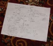
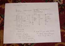
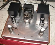
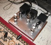
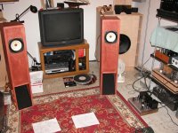
Here are the schematics in rough draft (not sure when if ever I will get around to drawing the real thing..) and a picture of the functional amplifier.
I have reinstalled the Canadian made GE 6J7G and think I might like them better. The metal Kenrads are quite good, but these sound a bit smoother.
The amplifier is sounding a bit smoother.
Note the gain is a bit excessive and you can probably use this with a passive line stage. Gain was calculated (not modeled) at ~18dB and it is at least this - oddly enough I did not actually measure the gain. Still more work to be done.
It is either smoothing out or I am getting used to it..
Build at own risk, potential is there, but work will be required, and good OPTs.
Attachments
Once I get the supply issues sorted out, I'm going to look at the square wave response and determine whether additional compensation is worthwhile or not. I played around briefly with a zobel on the primary of one of the OPTs and will spend some further time seeing whether this improves HF stability or not.
Some point I may look at reducing the open loop gain and commensurately reducing the closed loop gain as it is a bit on the high side.
Some point I may look at reducing the open loop gain and commensurately reducing the closed loop gain as it is a bit on the high side.
- Status
- This old topic is closed. If you want to reopen this topic, contact a moderator using the "Report Post" button.
- Home
- Amplifiers
- Tubes / Valves
- 6V6 Behavior W/Fixed Bias (SE Amp)