Hi guys.
The last couple of years I've been having some fun with head-fi. My mission was and still is, to find some cheap stuff and see what happens. I got some pretty serious HI-FI, but I just wanted to have fun with head-fi.
I just bought the cheapest diy tube pre amp kit I could find, and it comes with 2 6J1 tubes. I kinda believe they must be horrible, so the question is, can i get some quality tubes? and if so what would you recommend?
I don't know anything about tubes, and maybe the amp is so horrible it doesn't make much differens. But it could be fun to try.
Morten.
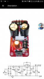
Yeah. It's this Kit.
6J1 Tube Preamp Amplifier Board Pre-amp Headphone Buffer Kits DIY Assortment K | eBay
6J1 Tube Preamp Amplifier Board Pre-amp Headphone Buffer Kits DIY Assortment K | eBay
Last edited:
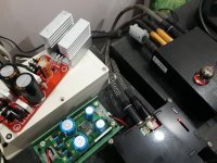
I have an entry preamp tube FX Audio Tube 03, already upgraded from new/original 6J1 to old 5654 tube, opamp 5532P to LME49860NA, linear PS LT1084CP. (all from aliexpress, except 5654 tube from Vietnam).
Is there any part to improve more?
Is there any part to improve more?
Attachments
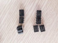
Those kits are terrible without mods . I built one and got a loud hum on one channel . Cutting and re-routing tracks or adding a separate DC heater supply helps but the design itself is not really hifi . Also the tubes supplied looked like the things had been pulled from a swamp . I bought three kits in total , only 2 tubes out of six tested adequately . The other four suffered from low emission , shorts and poor heater to cathode insulation so probably a good idea to source some more tubes from a reputable dealer
cheers
316a
cheers
316a
Looks just fine...
Energy works: an open tube feeding the filament heating is started, when the impulse from zero-tension start to increase the hot filament tube, etc., also happens to boost boost finish, so this is the same with the 8 * 470 UF capacitor very clean filter, good power supply system will not have a buzzing, the filament is 12 V DC power supply, needs two tube is connected in series with a DC filament filament too in order Reduce noise.
Think that means use DC for heaters.
+1 on the too low voltage
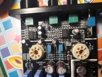
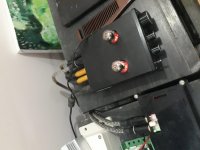
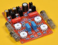
I bought this 4 tube line stage (see pic) for the hell of it. The built-in B+ PS was only about 60 volts. 3 of the 6N3 tubes measured so-so, the fourth had a huge H-K leak. The circuit held some promise. I traced it out and it's a Broskie Aikido. But the sound was crap. It probably needed 200 to 300 volts B+.
By the time you add two transformers (one for filament and one for B+) a Broskie Aikido 12Vac that runs on a single trans can be had for about the same $ and it sounds quite decent.
Steve
Attachments
It is a fairly safe bet that almost all cheap Chinese tube buffers/preamps are horrible. They usually use far too low a supply rail voltage. They often use a 6AK5/EF95 lookalike, which was designed for VHF/UHF (and is still quite good for that) but it is not especially linear even when used properly. The better ones just use it as a cathode follower, which can do little harm to the signal but does little good either. The worse ones use it as an amplifier, so you get distortion, noise and highish output impedance and probably too much gain.
Well I'm not surprised at all. I Actually said to my self that at least it could give me some extra soldering practice. I love soldering. I guess that will be it then. ")
My current is the Cmoy amp. And I haven't upgraded it yet, so that is my mission now.
Thanks to all of you guys who tapped in. I appreciate it.
My current is the Cmoy amp. And I haven't upgraded it yet, so that is my mission now.
Thanks to all of you guys who tapped in. I appreciate it.
Looks just fine...
Think that means use DC for heaters.
Sorry looking at the bits it now has DC for the heaters on the PCB. If they have done that they must have looked at the comments before and improved the design.

Last edited:
The grid stopper resistor is supposed to be right at the tube socket (with no other lead connected to the grid).
Anything else defeats the purpose and function of the grid stopper.
Schematic in post # 13 makes this mistake.
I see many schematics where they also make that mistake.
Anything else defeats the purpose and function of the grid stopper.
Schematic in post # 13 makes this mistake.
I see many schematics where they also make that mistake.
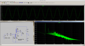
Here's an LT spice simulation.
Gain x8 THD for .8V pk output .3%
Screenshot from 2019-11-05 16-40-56.png
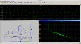
If you believe the spice model at low voltages go pentode add a little NF you can do wonders.
Screenshot from 2019-11-05 17-08-51.png
Gain x8 THD for .8V pk output .3%
Screenshot from 2019-11-05 16-40-56.png
If you believe the spice model at low voltages go pentode add a little NF you can do wonders.
Screenshot from 2019-11-05 17-08-51.png
Attachments
Last edited:
The crude half-wave-rectified DC inadequately-smoothed heater supply could be worse than AC heating.
I cannot think of a legitimate purpose for such a poor circuit in a domestic audio setup, apart from lining the pockets of the seller.
Yes replace D1 with full wave rectifier. Should the 100k output resistors go to ground not -28V.
- Status
- This old topic is closed. If you want to reopen this topic, contact a moderator using the "Report Post" button.
- Home
- Amplifiers
- Tubes / Valves
- 6J1 tubes quality?