Hi everyone, it's been awhile since I posted here, but at last it's winter and time for some tube stuff. I've been working on a 6GK6 PP UL driven by a 6AN8, with a Blumlein Garter circuit for the cathode bias. I have one channel up and running (it's dual mono), but I think there is room for improvement. The amp seems way to easy to drive and has a bit of a ragged edge on the upper frequencies. The bass is good, but it seems overly bright. I thought some of you might take a look at the schematic and give your opinions. As allways, Thanks for the help, Jay
Attachments
Jay, Interesting circuit. I am not qualified to give any opinions on this circuit, but I do have some questions.
(1) Don't you have three types of feedback: from the OT to the screen, unfiltered cathode, and also the tap from the cathode resistor divider to the grid of the other tube?
(2) Is the 6GK6 the tube that these component values were intended for?
(3) Possibly the 6BQ5 transformer is not right for this setup.
It seems to me that such a circuit would require careful choice of component values.
What specific circuit does the word "ultra-linear" come from?
I looks like it could be ultra-linear if everything is accounted for.
I'm basically curious to see what you say. No criticism intended. Mark
I don't see a cathode resistor for the first stage... what value? Split for feedback or using it all? The screen bypass should be returned to the cathode rather than B+. I would definitely bypass the output cathodes - you'll lose a lot of power and raise the output impedance without.
6BQ5 and 6GK6 should be identical except for pinout,
6BQ5 and 6GK6 should be identical except for pinout,
I'm sorry guys, I do have a resistor from pin 9 to ground (value is 1K). I'll look at the other points you made today and see if I can figure out some answers. This is my first PP amp, and one of my first attempts at drawing a schematic. I really appreciate the responses, because it seems like this is the only way I can learn. Reading the books doesn't seem to get it through my thick skull. Basically this circuit follows the Heathkit AA151 amplifer (which the OPTs came out of) very closely except for all the gain stages and tone controls before the 6AN8. I also added the .068 cap and grid leak resistor as a filter to enable the use of larger value coupling caps from an old post of Eli Duttman that I dug up. The Blumlein Garter circuit for the output cathodes was found with the help of Bandersnitch. So far I have learned more from this amp than any before. Thanks for the replies, Jay
BTW, this is the thread that inspired me. I found it while recapping a AA151 for a friend.
http://www.diyaudio.com/forums/showthread/t-70726.html
http://www.diyaudio.com/forums/showthread/t-70726.html
Tom Bavis said:I don't see a cathode resistor for the first stage... what value? Split for feedback or using it all? The screen bypass should be returned to the cathode rather than B+. I would definitely bypass the output cathodes - you'll lose a lot of power and raise the output impedance without.
6BQ5 and 6GK6 should be identical except for pinout,
Ok, to clarify, I do have a cathode resistor on pin 9 of the 6AN8, the value is 1K. The screen bypass is actually connected to ground at this time (I really mucked up my schematic drawing), but I will try moving it to the cathode. Could you explain the reason for this (I'm just trying to understand things). I was just starting to experiment with bypassing the cathode resistors on the 6GK6s. Is there a rule of thumb on the value, or a way to calculate bypass caps in general (this is something I've been wanting to learn as well).
All in all, the amp sounds pretty bad. There is no hum or anything like that, it just sounds slightly distorted throughout the frequency range. I feel like the 6AN8 is overdriving the 6GK6s, but I'm not sure how to decrease it. I guess I could increase the R of the 150k resistor between the AF amp and the phase inverter (pin 6 - 2), or would that mean I would have to change the values of the cap and resistor to ground from pin two?
As far as the term "ultra linear" I was just refering to the OPT having screen taps. Thanks for your time guys, Jay
jaymanaa said:The amp seems way to easy to drive and has a bit of a ragged edge on the upper frequencies. The bass is good, but it seems overly bright. I thought some of you might take a look at the schematic and give your opinions. As allways, Thanks for the help, Jay
These sonic defects seem to be related to inadequate gNFB. "overly bright" bass is an underdamping problem, most likely related to the lack of adequate cathode resistor bypassing in the finals. This will increase the effective r(p) of the finals, and pretty much undo what the local NFB is trying to accomplish.
Edginess at the upper mids and highs is due to letting pentode nastiness through. I've done two such designs (using 807s and 6BQ6GTBs). If you're gonna do a pentode amp, you're gonna need adequate gNFB to tame that edginess. Of course, add too much and that will lead to a "subdued", solid statey sound. That's not much better.
It seems, at first glance, that the situation with pin 2 of the 6AN8 is that the grid needs a resistor to ground.
Keeping in mind that I have much to learn, it looks like the 300V through the undefined plate resistor at pin 6 is going to put the grid at the wrong bias. It needs to be negative.
This would surely distort everything.
Keeping in mind that I have much to learn, it looks like the 300V through the undefined plate resistor at pin 6 is going to put the grid at the wrong bias. It needs to be negative.
This would surely distort everything.
I think a pentode stage will have lower distortion with the screen bypassed to the cathode. Every other similar circuit (i.e. Dynaco) does this. It's always good to check the voltages in a direct-coupled circuit like this, as tubes vary, and you want close to 1/4 B+ on the phase splitter cathode, and 3/4 on the plate. This might be little higher than Heath's voltages, if your B+ is higher. If necessary adjust the value of the screen resistor. But it's less critical in this amp than in the Dynacos, since you need less drive to the output tubes.
For a cathode bypass cap, it should be much lower in reactance (at your lowest frequency of interest) than the cathode resistors. 39 Ohms (1/10 the cathode resistor) at 20 Hz is 200 uF - I'd consider that a minimum - 470 uF would be good. It's MUCH less important with a common cathode resistor - since the cathode currents are changing in opposite directions, the changes cancel out, until you drive it into class AB.
For a cathode bypass cap, it should be much lower in reactance (at your lowest frequency of interest) than the cathode resistors. 39 Ohms (1/10 the cathode resistor) at 20 Hz is 200 uF - I'd consider that a minimum - 470 uF would be good. It's MUCH less important with a common cathode resistor - since the cathode currents are changing in opposite directions, the changes cancel out, until you drive it into class AB.
Lots to do and think about now, thanks for ALL the great responses. I imagine it can be frustrating helping rookies like me, but I would be up the creek otherwise.
I got it sounding much better by increasing the R of the dropping resistor that feeds the 6AN8 its B+. That voltage was way too high at about 345. I got it down to about 285 and most all of the distortion is gone. The amp doesn't seem so touchy to the volume control either. After doing that, I measured 235v on the plate of the inverter, and 50 on the cathode. My main B+ going to the OPT is 365. I'm going to add some bypass caps on the cathode resistors of the outputs now, and then maybe play with the feedback some. Thanks Again, Jay
I got it sounding much better by increasing the R of the dropping resistor that feeds the 6AN8 its B+. That voltage was way too high at about 345. I got it down to about 285 and most all of the distortion is gone. The amp doesn't seem so touchy to the volume control either. After doing that, I measured 235v on the plate of the inverter, and 50 on the cathode. My main B+ going to the OPT is 365. I'm going to add some bypass caps on the cathode resistors of the outputs now, and then maybe play with the feedback some. Thanks Again, Jay
I got the bypass caps installed on the cathode resistors (300uf was what I had laying around) and it helped a bunch. I also installed a 10 ohm (yep 10 ohm) resitor from the input RCA to ground which seemed to help a ton. It still gets pretty loud, but I think that value could be adjusted up some. I do have another question; when I check the current on the 6GK6s, do I add the two resistors together in the Garter circuit. I'm unclear as to what the cathode is actually seeing to ground. Each resistor is 390ohms and I'm measuring 27 volts across them. Thanks, Jay
Oh, I tried to post a pic of it here, we'll see if it worked.
Oh, I tried to post a pic of it here, we'll see if it worked.
Attachments
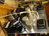
Heck, I just measured what the cathode of the output should be seeing and came up with 792 ohms. By putting ohms law to that with my 27v I come up with .92 watts. Can this be right? No wonder the 6GK6s aren't redplating. The RCA manual suggests 135 ohms for cathode bias. Does that mean I would want 75ohm resistors in the Garter circuit???
Upon further review, that would be 34mA which is pretty close to the 48mA that the manual suggests..........I think.
Upon further review, that would be 34mA which is pretty close to the 48mA that the manual suggests..........I think.
If your plate voltage is 360, and there's 27V on the cathode, then there's 333V across the tube. 333 X .034 is 11.3W plate AND screen dissipation, well within the tube's limits (13.2W plate, 2W screen). You push it up a little if you like (change the UPPER cathode resistors to 360 or 330) but I'd keep it under 13W total. Since this is class A, max output will go up in proprtion. Or leave it as-is if you'd like your output tubes to last forever...
The 130 Ohm value is for one tube at 250V or two tubes at 300 (it's like 260 Ohms per tube). Your supply voltage is higher, so you must use a higher value.
The 130 Ohm value is for one tube at 250V or two tubes at 300 (it's like 260 Ohms per tube). Your supply voltage is higher, so you must use a higher value.
I see, I think I will leave it as is. It really sounds very good to me now, and I think I'll wire up the left channel. I may play with the feedback a little first though. Thanks for sharing the hard earned knowledge everyone and I'll keep you all posted.
On second thought, I just re-read some of my Rozenblitz book to try and understand what I have learned here in the past couple days and he describes a neat way to optimize the OP of the pentode using a Harmonic Distortion Meter. I just ordered one and will wait untill it arrives to wire the left channel. I allways get more out of the books when I get help with pratical problems here. Now to re-read the chapter on Feedback.
On second thought, I just re-read some of my Rozenblitz book to try and understand what I have learned here in the past couple days and he describes a neat way to optimize the OP of the pentode using a Harmonic Distortion Meter. I just ordered one and will wait untill it arrives to wire the left channel. I allways get more out of the books when I get help with pratical problems here. Now to re-read the chapter on Feedback.
- Status
- This old topic is closed. If you want to reopen this topic, contact a moderator using the "Report Post" button.
- Home
- Amplifiers
- Tubes / Valves
- 6GK6 Ultralinear