Hi, I just finished building a 6B4G SE tube amp from a schematic I found online by Bill Howard. The issue is that the 6B4Gs keep red plating. I have rebuilt the cathode bias circuit twice and changed out the components as well. I decided to check double check the power transformer voltages and found that my power transformer was not 750V CT, but closer to 800V CT. The transformer was purchased off fleabay and is old stock. My question is how do I figure out the current draw of the circuit so that I can find a suitable dropping resistor? I would like to put the resistor on one of the legs on the transformer, before the rectifier so that I would not need such a large value.

I am using 5U4G for rectifier. I am getting 398 VAC per leg before rectification. I am getting 562VDC at the tie point that should be 450 VDC. The transformer is an unknown make and model (there aren't even any markings on it). I am using a separate transformer (toroid with dual 9v secondary) and separate regulated power supplies for the driver and power tube heaters. The only thing that I have done differently from the schematic is that I am using a 10H 200ma choke instead of the 6h 200ma.
Last edited:
Are you measuring the B+ PSU in a loaded down state? What the rail voltage is unloaded and what it is loaded down are quite different.
I took the measurements in an unloaded state; I did not want to run it with the tubes in If they are red plating.
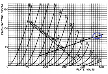
The tube is likely operating somewhere inside the blue circle which works out at 38watts plate dissipation (15watts is the limit for the 6B4  ) no wonder it´s redplating.
You can drop B+ voltage as you pointed out.
Assuming the tube will end up biased at 48ma that means a cathode potential of 57V and plate voltage of 300V (14,4watt plate dissipation), so we need to drop 562-300-57=205V. Assuming 10V from the OPT that leaves us at 195V. Assuming a total current draw of 48*2+8*2=112ma (8ma for each preamp section) you have to chuck in a 195/0,112=1750ohm resistor somewhere in the PS. No tube behaves exactly like the datasheet so your mileage may vary.
Another option as you have to drop so much voltage si to switch the PS to choke input filter. Just change the first PS cap and put it in parallel with the second one. The 562V should drop to somewhere around 450-460 so you would still need to put in a 600ohm or thereabouts resistor in series with the choke or the output tubes would be dissipating like 18watts.
) no wonder it´s redplating.You can drop B+ voltage as you pointed out.
Assuming the tube will end up biased at 48ma that means a cathode potential of 57V and plate voltage of 300V (14,4watt plate dissipation), so we need to drop 562-300-57=205V. Assuming 10V from the OPT that leaves us at 195V. Assuming a total current draw of 48*2+8*2=112ma (8ma for each preamp section) you have to chuck in a 195/0,112=1750ohm resistor somewhere in the PS. No tube behaves exactly like the datasheet so your mileage may vary.
Another option as you have to drop so much voltage si to switch the PS to choke input filter. Just change the first PS cap and put it in parallel with the second one. The 562V should drop to somewhere around 450-460 so you would still need to put in a 600ohm or thereabouts resistor in series with the choke or the output tubes would be dissipating like 18watts.
Attachments
Switch the rectifier from 5U4 to 5R4. At the rated 250 mA. draw, the forward drop in a 5R4 is 67 V.
Between choke I/P filtration and the rectifier change, the rail voltage should require, at most, minimal tweaking. The I/P inductor in a choke I/P filter is subjected to a great deal of stress. Either you use a part specifically rated for choke I/P service or you substantially derate the part you plan on using. A Hammond 193Q should be OK. Don't forget a high wattage 10 Kohm bleeder resistor across the 1st filter cap., to ensure that the critical current gets drawn.
Old editions of the ARRL Handbook indicate that LCLC is THE way to go, when choke I/P filtration is employed, which means you use the choke already on hand as the 2nd inductor.
Ok, so there is much to do here. Eli's advice is of course spot on, but I doubt you have a 2nd choke on hand.
I imagine you just want to get it to stop red-plating right now. I assume you have a variac and a good digital multimeter.
Try this:
1. Remove the 1st cap after the rectifier in your circuit.
2. Bring up the volts slowly with your variac and see if your choke vibrates. If it vibrating a lot then turn it OFF.
3. Check to see if your 6B4G's are still red plating. They shouldn't be. I they are, turn it OFF.
4. If it seems to be OK, measure your voltages and report them here. Anode, cathode, after rectifier, after choke.. everything. Be CAREFUL.
It is a VERY good idea to have a bleeder in this circuit somewhere to let the PSU caps lose charge after it is turned off. At least by-pass the 2nd filter cap with 3-5 watt 100k ohm resistor. I would suggest you do this step when you remove the 1st cap. Always measure all voltages on all caps to make sure your amp is SAFE before you work on it.
If the choke doesn't rattle, then its probably OK for choke input duty. Please give us as much information on the Choke and all parts.
Now here is what I would have done before building this (if I were you). I would have measured the mains transformer using my DMM and my variac to find out the winding ratio. Then I would have used PSU II to simulate my power circuit to make sure I don't get in trouble. I measure ALL mains transformers before I build btw - even NEW ones. Its really not hard to do this.
Lastly, there is a lot you can do to make this amp MUCH better. If you stick around then I'm sure you can make it work. No need for some "kit".
Ian
Last edited:
375 - 0 - 375 is about right for a supply. Whatever do you want DC heaters for? There is no need. The output valve is a bright emitter so should have its own filament supply.
Hi Jon - I don't think anyone mentioned anything about DC heaters yet...
375 - 0 - 375 is about right for a supply. Whatever do you want DC heaters for? There is no need. The output valve is a bright emitter so should have its own filament supply.
I am very grateful for all the help that I have received here. I am using DC heaters because that is what the schematic specified. From what I have read DC heaters are necessary with the 6B4G to avoid hum. I am not using the 6.3v tap on the main power transformer, instead I am using a single, separate toroid transformer with that has dual secondaries. Each tap is going to an LM317 regulated circuit (I built two separate, identical circuit boards), one of which is going to the two 6B4G tubes and the other is going to the 6SN7.
The choke I am using came from some old military radar equipment. The equipment was essentially a goldmine from which I gathered a bunch of transformers, chokes, big oil can caps, and a boat load of tubes. There were also separate boxed filled with NOS tubes, I saved what I could before they were destroyed
. For this project the only things that I am using that came from the above equipment are the 6B4Gs and the choke. I have other chokes, but the only one rated at 200ma (per schematic) is the one I am currently using. As for the main filter caps, they are NEW 60uf can caps rated at 375VAC. I have about 6 6B4G tubes on hand, but they are all old and used. I tested each of them on my BK 707 tester and they all checked excellent. I tested the tubes that red plated and they still check good . I will try and take some pictures of the inside of the amp, but I have to worn everyone, it isn't my best work and has turned into a birds nest from troubleshooting this issue.
Again, I really appreciate the help from everyone. I am going to go back and reread everything and continue trying to get this thing going when I get some time off work.
Each 6B4g should have its OWN separate filament winding.
Ian
Each tap is going to an LM317 regulated circuit (I built two separate, identical circuit boards), one of which is going to the two 6B4G tubes and the other is going to the 6SN7.
Are you saying you tied together the cathodes of the 6B4s of both channels?
- Status
- This old topic is closed. If you want to reopen this topic, contact a moderator using the "Report Post" button.
- Home
- Amplifiers
- Tubes / Valves
- 6B4G New Amp Build Issue