Hey guys, im working on a 24 to 12volts converter, the original mosfets was RU6099R all was destroyed along with TL494 and IR2011.
Im unable to get the RU6099R and i was trying to use IRF4310 but they are heating up. The gate resistors are 47ohms, should i increase them?
square waves are fine both for the HS and LS, tried two 50N06 for test and they ran cool at idle, but when i loaded up the 8pcs of IRF4310 im having heating issues at idle.
For a production design, you'd want to find something that's a happy-medium. Too low and you make the drive circuit work much harder. Too high and the FETs run hot. You can try 10s but I'd try several values between 47 and 10 to see the highest value that will allow the FETs to run cool. You don't have to have all of the FETs in the circuit except for final testing if the drive circuit is something like an EF pair or a dedicated gate driver IC. You can try one in each bank. The final value may need to be slightly lower than the value required for only 1/bank due to inefficiencies in the drivers.
Can 47ohms to 10ohms ok to be in the gate circuitry?
Too low a value could cause shoot-through.
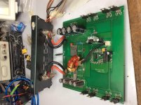
This is the circuit, just as simple as it gets just an inductor, no toroidal transformer.
Heating up on the fets with all proper drive signals LS and HS.
I haven’t changed the gate resistors as yet (just gotten in to work).
The originals was RU6099R, I also changed both drive IC’s.
The IRFB4310 have an higher rating on volts and current but I don’t know about gate capacitance or underlying factors why it shouldn’t work.
Attachments

Last edited:
I didn’t do the experiment, I just went for 22ohms it’s cooler (drawing 0.18amp at idle).
I only did the high side bank as they were the fastest to heat up, should I change also the low side gates? (Well obviously I’ve never seen different gates within a dual bank design).
I only did the high side bank as they were the fastest to heat up, should I change also the low side gates? (Well obviously I’ve never seen different gates within a dual bank design).
I have adjustable bench PS, it’s just used on a 24volt vehicle to supply 12volts at (not exceeding 60amperes) for some headunit, drop down roof DVD player and a small amp.
But for your test I could swing it around upper or lower 24volts to see if it’s stable and thermally safe.
I’ve not the manual to know the parameters but I take it down to 18volts and it’s stable at 12.95volts minimal temp on the ic but one fet on the low side have a little temp but not hot to handle just a tad warm. Same to 26volts. There was adjusted duty cycle during the tests.
- Status
- This old topic is closed. If you want to reopen this topic, contact a moderator using the "Report Post" button.
- Home
- General Interest
- Car Audio
- 24v-12v DC to DC Converter