I got some RCA 1625 I love to build a tube radio using it. I wanted to check if anybody has any experience? there are some Radio schematics on the web
take a look at these and enjoy:

take a look at these and enjoy:
An externally hosted image should be here but it was not working when we last tested it.
An externally hosted image should be here but it was not working when we last tested it.
An externally hosted image should be here but it was not working when we last tested it.
An externally hosted image should be here but it was not working when we last tested it.
An externally hosted image should be here but it was not working when we last tested it.
An externally hosted image should be here but it was not working when we last tested it.
An externally hosted image should be here but it was not working when we last tested it.
Google tells me that the 1625 is a version of the 807 output beam tetrode. I know enough about valves and radio not to use one as a radio receiver, except possibly as the audio output stage. Radio transmitter, yes, but for that you need a licence and the knowledge to obtain a licence.
This isn't useful except as some kind of a dull art project. As DF96 said, it's a waste of a good tube.
You don't really need experience for something like that. It's no Superheterodyne or PLL, just a simple regenerative receiver consisting of a single tube which does all the work (and it does that badly). Here is everything you need to know: Regenerative circuit - Wikipedia, the free encyclopedia
You don't really need experience for something like that. It's no Superheterodyne or PLL, just a simple regenerative receiver consisting of a single tube which does all the work (and it does that badly). Here is everything you need to know: Regenerative circuit - Wikipedia, the free encyclopedia
It was used several years as RF and AF power stages in AM transmitters, in 80 to 20 meters hams bands (3500 to 14000 KHz), and a couple of them are capable of modulate a 100W AM emitter in class AB2. There was a common set made by two of them in parallel feeding a PI LC tank, and transformer modulated by other two of them in Class AB2 and a couple of 866 mercury vapor rectifiers. I had one of them several years ago. In ham radio, specially at AM modulation levels, audio quality is not a priority, and the usually shorts duty cycle permits these configuration. Keep in mind, that to modulate a 200W AM transmitter, is needed only a 100W AF output, hiding the performance in RF (Class C)and AF (Class AB) plate efficiency.
Last edited:
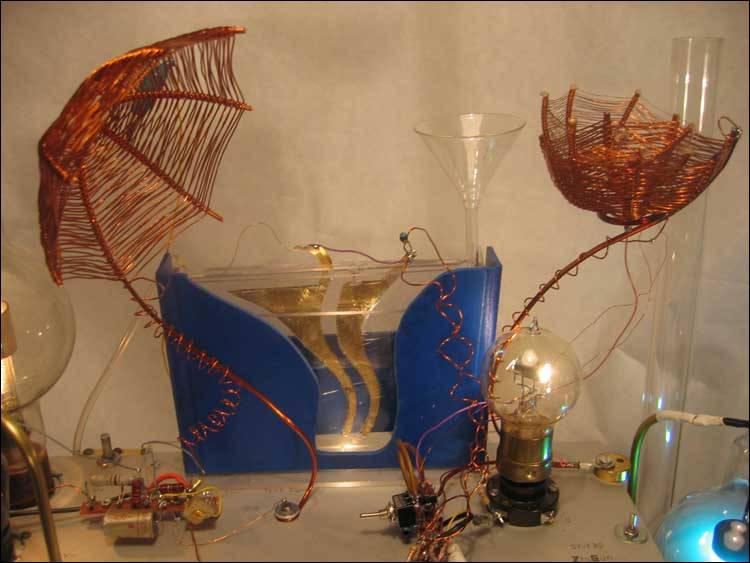
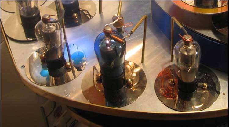
Real men build something like this: Das Hydradio-Projekt, von Hermann Scharfetter
Even has a mercury vapor heater rectifier !
The GU81 regenerative receiver is nice, too: GU81
Even has a mercury vapor heater rectifier !
The GU81 regenerative receiver is nice, too: GU81
Real men build something like this: Das Hydradio-Projekt, von Hermann Scharfetter
http://www.b-kainka.de/Weblog/HF/GU81.htm
LOL That doesn't look too masculine. Unless you mean ugly/manly. And no, I don't like the 'arty' radios either. Now that I think about it most vintage radios are nice looking, in those days it was easy to find a beautiful radio - not anymore. Same can be said about tube amps.
Been there; done that.
That was my first foray into electronic design: a regen variation that used a 1624, operating at 600Vdc. I was ten y/o at the time, had little idea as to what the hell I was doing, but it worked. I needed to add fixed bias to prevent red plating, as the usual grid leak bias wasn't getting the job done, and so needed to be supplemented with external bias.
It worked, and was basically a "just because I could" project.
If he's going to the time and expense of making this Rube Goldberg contraption, you'd think he could invest in some proper plate cap connectors, wouldn't you?
A regen with 600VDC? Are you crazy?
Not crazy, just ten years old at the time.

Not crazy, just ten years old at the time.An externally hosted image should be here but it was not working when we last tested it.
I have some experience in regens, in fact I have build a couple of them.
Such high voltage in regens only cause troubles:
1) Excessive plate disipation because no fixed bias is allowable, in the case no detection can have at lower input signals than this fixed bias,
2) The control to adjust the regeneration amount, becomes too hardly to set, in fact as too low voltages are used, this adjust becomes more soft.
3) Pentodes with high transconductance are also difficult to adjust. The boundary between oscillation and no-oscillation is very tiny, and extremely difficult to find. The lower mu triodes with as low plate voltage as you can, in this way of working are the best suited for it.
For more details, there is a very interesting info at:
Dave's Homemade Crystal and Tube Radios at makearadio.com.
- Status
- This old topic is closed. If you want to reopen this topic, contact a moderator using the "Report Post" button.
- Home
- Amplifiers
- Tubes / Valves
- 1625 tube radio?