12AX7, EL34 or 6L6 design waned
Hi
I am wanting to start building my first valve amp. As a first project I would like something around the 20watt mark, and do it cheap! I have found this website that uses a 100volt impedance matching transformer as the output tran. http://www.alphalink.com.au/~cambie/6AN8amp/Grant_Wills_6CM5amp.htm
I would like to do something similar but I want to use valves that I have avaliable from local electronics shops. As stated in the website the transformer is 8k:8ohm.The valves I have avaliable are 12AX7, EL34 and 6L6. I assume the design would be PP. So if you have a design for such an amp please post it!
More details?
Hey.
8k seems a :little: high for 6l6...that is more in the el84/6V6 territory...BUT it can be done.
What topology are you looking at, and what will it be used for? Phono? Home Stereo? Will you need a preamp section?
It sounds like a push pull tranny that you will be using. And what is your price-to-tone ratio? If you just want to experiment with tubes, you could try a sinple output stage, like a self-split and eliminate the need for a phase splitter tube, thus keeping the current/voltage demands on the power supply lower, but they are not super popular...one of those lost designs I guess.
Somrthing like this?
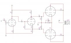
I just whipped this up as an example of a super simple circuit. It uses a concertina (split-load) driver with 1 gain stage before it, and runs the 6L6's in cathode bias/triode connection...simplest design I could thing of in the push-pull realm. You could use a 12ax7 as the driver/splitter, but the output impedance would be a bit high, a 12au7 would be a bit better, but either will function.
I just whipped this up as an example of a super simple circuit. It uses a concertina (split-load) driver with 1 gain stage before it, and runs the 6L6's in cathode bias/triode connection...simplest design I could thing of in the push-pull realm. You could use a 12ax7 as the driver/splitter, but the output impedance would be a bit high, a 12au7 would be a bit better, but either will function.
Attachments
Hi aletheian
I will be using it for home stereo. A pre amp is not 100% nessary, but if there is a simple all in one solution then great. I can buy a vavle preamp as a kit from a local electronics store so I could go that route for the preamp.
Thanks for making that schematic! Since I am new to valves and their design do you have component values?
One question about power supplies, say I need 2 voltages ie 250volts and 6.3volts for the heaters, can I run the heaters off a seperate transformer?
Xfrmers
Hey man,
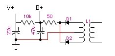
There are TONS of psu schematics floating around this website. The simplest type is the 'ol "brute force" unregulated supply...that should work fine for a first amp attempt. You could probably do it with as little as 2 diodes, 2 resistors and 2 capacitors in a simple RC filter circuit...like an old Dynaco.
I drew up an example diagram, but you can up the value of the capacitors to lower the ripple/noise if you want, AND if you really want to get spunky, replace the 50 ohm resistor with a choke (I would recommend placing another capacitor before the choke if you take that route.
For the heaters, find any 12v or 6v power transofrmer with a sufficient current rating and it should be cool...somewhere around 2.5 Amps for 6L6's, or 3.5+ for EL34's. I did a project with a little transformer that I bought from Radio Shack once...dunno if they still sell them though. Hammond makes some nice cheapish ones. You could also get a main power transformer with a 6v heater tap too, that would be easier. Just take the voltage rating (175-0-175 for emample) add it up (175+175=350v) and multiply by .7 (350x.7=245v) to estimate ABOUT what plate voltage you will end up with. You'll lose a bit in the psu resistors, and in the rectifier too. As for the current, add the plate current at your bias point + grid current. The 12ax7 will draw a few milliamps, so don't worry about that. A good guess is around 125mA, but more available current is always better.
I'll work on putting in some general component values tonight, but you might want to try it yourself if you like math. The Aikenamps.com website has some killer info and all the formulas that you need. Since you only have one gain stage to play with, use that to set your EQ cutoffs from 20Hz to 20kHz.
Hey man,
There are TONS of psu schematics floating around this website. The simplest type is the 'ol "brute force" unregulated supply...that should work fine for a first amp attempt. You could probably do it with as little as 2 diodes, 2 resistors and 2 capacitors in a simple RC filter circuit...like an old Dynaco.
I drew up an example diagram, but you can up the value of the capacitors to lower the ripple/noise if you want, AND if you really want to get spunky, replace the 50 ohm resistor with a choke (I would recommend placing another capacitor before the choke if you take that route.
For the heaters, find any 12v or 6v power transofrmer with a sufficient current rating and it should be cool...somewhere around 2.5 Amps for 6L6's, or 3.5+ for EL34's. I did a project with a little transformer that I bought from Radio Shack once...dunno if they still sell them though. Hammond makes some nice cheapish ones. You could also get a main power transformer with a 6v heater tap too, that would be easier. Just take the voltage rating (175-0-175 for emample) add it up (175+175=350v) and multiply by .7 (350x.7=245v) to estimate ABOUT what plate voltage you will end up with. You'll lose a bit in the psu resistors, and in the rectifier too. As for the current, add the plate current at your bias point + grid current. The 12ax7 will draw a few milliamps, so don't worry about that. A good guess is around 125mA, but more available current is always better.
I'll work on putting in some general component values tonight, but you might want to try it yourself if you like math. The Aikenamps.com website has some killer info and all the formulas that you need. Since you only have one gain stage to play with, use that to set your EQ cutoffs from 20Hz to 20kHz.
Attachments
Try this out
Hey man,
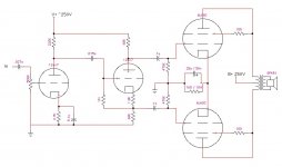
I ran a little math and here is what I came up with. It uses no gobal feedback, otherwise the specs would chance. There is some local feedback in the form of the first stage cathode resistor...and I suppose you could add some high value resistors from the plates to the grids of the output tubes for some local feedback there is you want, but I wouldn't worry about that right now.
The potentiometer at the input WILL alter your input freq response as it is turned down, so either take it out and replace it with a fixed resistor if youe source has an output control, OR experiment with the input DC blocking cap value until you like the sound...or take out the cap and lower the value of the input pot...but that will change the gain of that stage...just stuff you can try.
You will probably want to put some grid resistors on he output tubes...I forgot to draw those in...just to be safe if the tubes start drawing crazy current. 1K should be cool. Just run them from the 470K resistors to the input grids instead of connecting them directly.
ALSO, I just did the load lines real quick for the output tube cathode bias resistor...i think it is cool, but you might want to check around or do the math yourself. You can err higher if you want to play it safe, take the mesurements when it is built and adjust accordingly.
Hey man,
I ran a little math and here is what I came up with. It uses no gobal feedback, otherwise the specs would chance. There is some local feedback in the form of the first stage cathode resistor...and I suppose you could add some high value resistors from the plates to the grids of the output tubes for some local feedback there is you want, but I wouldn't worry about that right now.
The potentiometer at the input WILL alter your input freq response as it is turned down, so either take it out and replace it with a fixed resistor if youe source has an output control, OR experiment with the input DC blocking cap value until you like the sound...or take out the cap and lower the value of the input pot...but that will change the gain of that stage...just stuff you can try.
You will probably want to put some grid resistors on he output tubes...I forgot to draw those in...just to be safe if the tubes start drawing crazy current. 1K should be cool. Just run them from the 470K resistors to the input grids instead of connecting them directly.
ALSO, I just did the load lines real quick for the output tube cathode bias resistor...i think it is cool, but you might want to check around or do the math yourself. You can err higher if you want to play it safe, take the mesurements when it is built and adjust accordingly.
Attachments
Thanks alot for your help! With the volume control, why is it that varying the pot changes the freq responce?? What if I replaced that with a fixed value and added a 50k pot before the input? I might try for a bit more of a refined power supply. What sort of wattage would you expect for this thing to put out?? Hopefully once I get my 35mm projector back together and off my desk I can start on this amp!
Don't start 'in a hole'
Interesting how hundreds of designs use less than best quality tube types- go figure. One has to consider all the handcraft work required to achieve a less than best sounding amp- no thanks! Also consider the DIY amp is hard to sell vs upgrading a vinatge amp.
Well known tube type great performers are Sylvania or Tung-Sol 6P5GT, RCA 6J5GT & Sylvania 6SN7GT. Power tubes vary a lot & one must consider power needed. For the most part, triode connected tetrodes perform best, but at 1/2 power. A regulated screen supply is inportant with tetrode connected tubes, however use a choke & poly or oil cap after that regulator. As for Ultra Linear, I consider that to mean Un Linear (stay away).
15-watts? Use PPP Sylvania 6V6GT triode connected or inexpensive $2 NOS Sylvania 5V6GT with a dropping resistor at filament (Radio Daze in the state of New York). Sweet sounding tubes.
See the 'poinz' design, but use a 6P5GT or a 6J5GT driving a Sylvania 6SN7GT or a pair of lower cost 6J5s for the phase splitter. BTW- The RCA metal 6J5 sound as good as the RCA glass 6J5GT. Not true of other metal 6J5s I listened to. I seen NOS on ebay for $2 each.
30-watts? triode connected Sovtek 6550 with rectangle shape plate holes, not the old stock inferior Sovtek 6550s with the round plate holes (please).
Hope this helps.
Hi Fiat
Up to now nobody seems to have replied to your post#8, so let me try to help (I will explain simply and fully so this will be a little long.)
Firstly, the high frequency response will suffer with any appreciable input resistance. The main culprit is what we call Miller capacitance that is shunting your input. The highest input resistance with a 500K pot will be when the rotor is in the middle (resistance-wise). There you will have 250K to common in parallel with another 250K up top, also essentially in parallel with the first 250K, if the input source impedance is considered negligible for now. That brings us to 125K.
The main contributor to input capacitance is the 1.7 pF between anode and grid. This sounds low, but this capacitance is not to common, but to the anode, which for every volt across it from the grid side, has about 70V in the opposite direction on the other side from the anode (the amplification of the first tube will be about 70). The effect of this is that the grid "sees" an equivalent capacitor of 71 x 1.7 = 120pF. When this appears after the above 125K resistance, you will have a 3dB attenuation at 10KHz. If your source impedance is significant, this will be lower. There is also other internal capacitances acting here which I have ignored for simplicity sake.
You can now work out that at either end of the pot, the nett series resistance will be less and the frequency cut-off higher. Thus you will have worst attenuation of treble with the pot in the middle (resistance wise).
As an aside, this is why I am not fond of the high mu ECC83 as an input tube unless one can guarantee a low source impedance - and then not with a volume control in the way! Your best solution here is to use a 100K volume control if your input source is not shunted too much by that.
The expected output power will be about 8W into 8K transformer primary impedance. With only 250V applied the 6L6s are rather wasted. Once you get this to work, you can increase that to 450 - 500V with about 300 ohm common cathode resistor (10W). That should increase available output power to about 14W, depending on the output transformer.
Using the distributed load (UL) configuration can convert this circuit to give about 40W - a worth-while increase (at 450V h.t.). I must respectfully disagree with Amperex about the non-linearity - that is not what I have found or what my data shows (I have graphs from G.E.). UL allows one to mainatin about 80% of the advantages of triodes (low internal impedance and low distortion) but with about pentode output power. But perhaps that is for another day, if you want to start with the circuit as is.
Good luck!
Most respectfully
Tetrodes respond best with a regulated screen as long as the regulator has some isolation from that regulator that can produce noise. Or, an option is a stiff seperate supply.
A better sounding amp simply uses a triode, but higher power triodes such as 845 are costly. A compromise is some tubes respond well to triode connected such as the 6V6GT.
UL has always produced the worst sounding amps of the lot & I will never go back to them. I consider UL a waste of time & money.
I like neutral sounding amps. The word 'warm sounding' just means audio distortion to me. Once one hears a fast & neutral amp, they can not go back to the mud.
Thanks for your replies! Johan Potgieter, thanks for the great explination. I might increase the 250volts, since I have a schematic for a power supply using 2 off the shelf transformers conected back to back. They are both 160VA, with the first supplying 25VAC to the 30VAC center taped secondary winding of the second transfomer. At full load that will produce 150VAC which feeds a voltage double cct. This produces +480V. Or is there an easier way? If I could increase it to 14watts approx to start off with thats about what I am after. If all goes well then I will want to to increase the power to 40watts as sujested and possibly make my home theatre setup run of these.
No fine, Amperex, I respect your views - and ears!
I would agree that used as a tetrode a regulated supply is required. Many "bit the dust" by feeding beam tetrode screens off the supply for the rest of the amplifier, where this was resistor-decoupled. I have even seen commercial designs that way.
I would also agree with the meaninglessness of terms like "warm" and "musical" and a host of others, however well intended. The latter sounds especially pious and seems to be something with which one can hardly disagree, but leaves one with the impression of an amplifier with the kind of harmonic content (addition) that makes the music sound "better". The customer can naturally buy with his money what he likes, but a lot of unnecessary ill-will resulted when the argument branched out to "A is better than B" instead of simply staying with "I (personally) prefer A to B".
Johan Potgieter said:Hi Fiat
Up to now nobody seems to have replied to your post#8, so let me try to help (I will explain simply and fully so this will be a little long.)
Firstly, the high frequency response will suffer with any appreciable input resistance. The main culprit is what we call Miller capacitance that is shunting your input. The highest input resistance with a 500K pot will be when the rotor is in the middle (resistance-wise). There you will have 250K to common in parallel with another 250K up top, also essentially in parallel with the first 250K, if the input source impedance is considered negligible for now. That brings us to 125K.
The main contributor to input capacitance is the 1.7 pF between anode and grid. This sounds low, but this capacitance is not to common, but to the anode, which for every volt across it from the grid side, has about 70V in the opposite direction on the other side from the anode (the amplification of the first tube will be about 70). The effect of this is that the grid "sees" an equivalent capacitor of 71 x 1.7 = 120pF. When this appears after the above 125K resistance, you will have a 3dB attenuation at 10KHz. If your source impedance is significant, this will be lower. There is also other internal capacitances acting here which I have ignored for simplicity sake.
You can now work out that at either end of the pot, the nett series resistance will be less and the frequency cut-off higher. Thus you will have worst attenuation of treble with the pot in the middle (resistance wise).
As an aside, this is why I am not fond of the high mu ECC83 as an input tube unless one can guarantee a low source impedance - and then not with a volume control in the way! Your best solution here is to use a 100K volume control if your input source is not shunted too much by that.
The expected output power will be about 8W into 8K transformer primary impedance. With only 250V applied the 6L6s are rather wasted. Once you get this to work, you can increase that to 450 - 500V with about 300 ohm common cathode resistor (10W). That should increase available output power to about 14W, depending on the output transformer.
Using the distributed load (UL) configuration can convert this circuit to give about 40W - a worth-while increase (at 450V h.t.). I must respectfully disagree with Amperex about the non-linearity - that is not what I have found or what my data shows (I have graphs from G.E.). UL allows one to mainatin about 80% of the advantages of triodes (low internal impedance and low distortion) but with about pentode output power. But perhaps that is for another day, if you want to start with the circuit as is.
Good luck!
Yeah...what he said... sorry, I have been away for a while. There are definately better ways to tweak the design... I was going for 'quick and dirty' with the lowest component count possible.
PEACE!
One other detail... this might be assumed, but I wasn't sure if this came across. If you increase to a higher plate voltage, then run the debate is to run it in Ultralinear or tetrode, which means you would have to change the grid configuration and potentially the power supply. new manufacture tubes in triode at 480V should work out, but it makes me nervous...
Yah. . . . know the feeling. I am at present in the last stages of finishing a 120W amp using a nett 520V anode and 460V screen voltage (4 x 6L6GC in the Quad II type output stage). Having become used to transistors I approach carefully - hope no smoke and "spitzensparken". Folks may have noticed that I was looking for extra genuine GE - 6L6GCs on another thread; if unavailable (as it is beginning to look) I will be going to Svetlana or ...EH - then my turn to be nervous.
So what do I need to modify if I want to increase the B+ volatge? Can I still use 12AX7's and a volatge of around 400volts? I ask this becuase the specs for a 12ax7 say a max plate voltage of 300volts? Or would a resisitor be used for their plates to drop the volatge? I am new to valve amps and their designs so bare with me, I am still doing reading on the subject. Thanks for all the help up to now!
Firstly you can certainly use the ECC..s with a supply of 450V (seems to be a popular voltage for this sort of thing, probably because that is a popular rating for high voltage electrolytic caps).
One manual I have gives absolute max. for ECC83 as 600V, operating as 330V. The max. voltage rating is somewhat coupled to the dissipation and other factors - it does not mean it will start sparking inside at 340V! The thing not to exceed is the maximum anode dissipation (apart from keeping the heater voltage within spec.).
Then also notice that voltage amp. stages are decoupled from the main supply by say 22K (and 16UF/450V cap), making the voltage there no more than about 350V - 380V. Then you still have the anode load resistors. This is a longer story, but one tries to put the final anode voltage where the maximum required sine wave will just fit in with say about 20V above the G1 = 0V curve on the anode voltage/anode current load line.
Sorry that this comes to you rather disjointed - at which circuit are we now - if it is post #3 by Aletheian, perhaps I can hook up a practical circuit in a day or 2 (if he does not come first) and give you ball park values.
- Status
- This old topic is closed. If you want to reopen this topic, contact a moderator using the "Report Post" button.
- Home
- Amplifiers
- Tubes / Valves
- 12AX7, EL34 or 6L6 design wanted