Ok, I've got a weird problem. I'm probably overlooking something obvious but I can't see it.
I've got a preamp section in an amplifier which is divided in two sections, each powered from its own 12VAC winding from an auxilliary transformer.
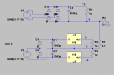
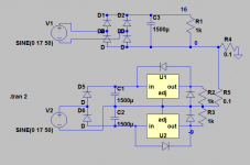
The first section is using a diode bridge to create a single supply (+17v). The second section is using a full wave voltage doubler, to create a +/-17V supply or so. This supply is then regulated down to +/-9V by lm7809/7909.
If there is no signal ground connection between the two preamp sections, everything starts normally. However, if I connect the two preamp sections by a signal cable (signal+gnd), there is 0V at the output of the lm7809. There is 17V at its input (and there is -9V at the output of the lm7909, -17V at the input). If I quickly switch off and on the amplifer, the problem disappears and all my voltages are ok.
Any idea ?
I've got a preamp section in an amplifier which is divided in two sections, each powered from its own 12VAC winding from an auxilliary transformer.
The first section is using a diode bridge to create a single supply (+17v). The second section is using a full wave voltage doubler, to create a +/-17V supply or so. This supply is then regulated down to +/-9V by lm7809/7909.
If there is no signal ground connection between the two preamp sections, everything starts normally. However, if I connect the two preamp sections by a signal cable (signal+gnd), there is 0V at the output of the lm7809. There is 17V at its input (and there is -9V at the output of the lm7909, -17V at the input). If I quickly switch off and on the amplifer, the problem disappears and all my voltages are ok.
Any idea ?
I hope V1 and V2 are separate windings....
Anyway, try connecting an anti-inversion diode between GND and OUT of each regulator; preferably a schottky type, like 1N5818 or otherwise a large standard rectifier like 1N5401
They are separate of course
")
Out of curiosity, why schottky or 1N5401 rather than 1N4001 ?
I suggest you throw away the half wave doubler.
Bridge rectify the two windings and series connect the outputs for a dual polarity supply.
Then regulate that down to your ±9Vdc
You still have the 17Vdc unregulated.
Since you have both -ve & +ve regulators, you also have the option to series connect the windings and use one bridge rectifier to create your ±9Vdc as well as the ±17Vdc unregulated.
Did you isolate the tab on the -ve regulator?
I would monitor the inputs to the regulators and make sure the 0v line is centred.
It's a low current applications for the +/-9V (an opa4134 so about 16ma) so there is no heatsinks on the regulator. Still 16ma should be enough as a minimum load for the lm7809.
The 0V line is perfectly centered (+/-17V at the inputs of the regs).
If the anti-inversion diodes suggested by Elvee don't do the trick, I'll go that way. Since the rectifiers are on the PCBs of the two sections (one powering a motorized pot and some relays, the other powering the audio preamp), I'd rather avoid it if I can, to minimize new wiring, etc.AndrewT said:I suggest you throw away the half wave doubler....
edit: It's really a startup problem. As I said in the first post, quickly powering the amp on, off and on, everything is fine. It's only when started "cold" that I've got a problem.
Hi Ben,
When using the 78xx and 79xx regulators, there are two recommended diodes. Elvee showed you one pair that prevents them from locking up on start up. You only need the 1N4002 or higher. Additionally, you should have reverse biased diodes between the input and output circuits. This diode prevents the part from damage due to discharging load capacitors, or a sudden short in a main filter capacitor. You can see these in some application notes. Again, 1N4002 rectifiers are all you need.
Many times these diodes are priced the same up to the highest voltage. If so, buy some extra 1N4007 diodes or whatever the highest breakdown voltages you can find as a 1N400x rectifier. They are fine rated at 1 ampere as the three terminal regulators are mostly rated for the same in a TO-220 package. I doubt you would ever use one at it's full current rating.
Best, Chris
Apparently, the locking up appears when the output voltage reaches about -1Vbe (probably a parasitic transistor turning on, or something similar).Out of curiosity, why schottky or 1N5401 rather than 1N4001 ?
When you use a Si diode to clamp the output, the residual voltage might still be too high if the inversion current is too high. A schottky covers all the possibilities.
In the 70's, we were advised to use Ge diodes, because at that time schokttky's were luxurious and expensive rarities.
Problem, at the same period power Ge diodes had become equally rare and most of the time, the only realistic solution was a redesign of the supply to enforce a proper sequencing.
Fortunately today schottky's are almost as cheap as the sand they are made from
Apparently, the locking up appears when the output voltage reaches about -1Vbe (probably a parasitic transistor turning on, or something similar).
When you use a Si diode to clamp the output, the residual voltage might still be too high if the inversion current is too high. A schottky covers all the possibilities.
In the 70's, we were advised to use Ge diodes, because at that time schokttky's were luxurious and expensive rarities.
Problem, at the same period power Ge diodes had become equally rare and most of the time, the only realistic solution was a redesign of the supply to enforce a proper sequencing.
Fortunately today schottky's are almost as cheap as the sand they are made from
Thank you for the explanation. I've got some sb160 on hand, I'll try with those tomorrow.
In fact, it is highly variable between manufacturers.Hi Elvee,
The standard 1N400x series also work fine for this. No need for the more expensive rectifiers.
-Chris
I made a quick check, first on a 7805 Motorola, which I remember were particularly sensitive.
The inversion current needs to be >2mA for the locking to occur. That is indeed very low. In order to allow the start-up, the negative voltage cannot be greater than ~700mV, which corresponds to ~10-20mA for a typical 1N400x.
Thus, the 1N400x would work when the problem is not too severe.
If the 7805 is hotter than the diode, things degrade very quickly, because the internal Vbe's are correspondingly smaller.
I made the same test on a ST 7805, and there I wasn't able to cause a lock up (I limited the maximum unclamped inversion current to 20mA because I didn't want to damage the part).
Thus, some 78xx will even work without any diode at all.
These are probably two extremes, but to be on the safe side, a schottky or large junction Si diode is preferable
have literaly used hundreds of 78xx ,79xx in hundred different applications,and from different manufacturers.have never put diode , never got any problems at all.only once i got behaviour like this but that was when intentionaly exceeding max Vdrop.
now i am interested what manufacturer was your 78xx,79xx couse i have 50 of untested pairs that i bought at local electronic shop for around half dollar /piece ,most i think is fairchild semi ,i hope yours werent fairchild.
now i am interested what manufacturer was your 78xx,79xx couse i have 50 of untested pairs that i bought at local electronic shop for around half dollar /piece ,most i think is fairchild semi ,i hope yours werent fairchild.
It is only a combination of input sequence + type of load that can show such a problem.have literaly used hundreds of 78xx ,79xx in hundred different applications,and from different manufacturers.have never put diode , never got any problems at all.only once i got behaviour like this but that was when intentionaly exceeding max Vdrop.
now i am interested what manufacturer was your 78xx,79xx couse i have 50 of untested pairs that i bought at local electronic shop for around half dollar /piece ,most i think is fairchild semi ,i hope yours werent fairchild.
Otherwise, you can use them by thousands and never notice anything, even if they are of the most sensitive variety.
Hi Elvee,
Interesting findings. If I ever have this situation occur that a 1N400x doesn't cure, I'll try a schokttky diode.
I build mostly prototypes and work on poorly designed equipment that can't be repaired in the normal way. I have seen lot's of these three terminal regulators lock up, but so far a 1N400x has always corrected the situation. I normally use On Semi or Fairchild parts, but Central Semiconductor parts also work fine.
-Chris
It is quite possible that the ONsemi's have undergone one or more revision since the original MC7805 type I tested: after all, the one I tested carries a 8116 date code, probably older than many DIYaudio membersI normally use On Semi
The ST one is a youngster in comparison: from 9940. It is entirely possible that the original SFC2805 was as poor as the Moto.
With two supplies, the test is very easy to do, and it is instructive. If I find other interesting samples and some spare time, I will also test them
- Status
- This old topic is closed. If you want to reopen this topic, contact a moderator using the "Report Post" button.
- Home
- Amplifiers
- Power Supplies
- 0V output with a 7809 at startup