I have a pair of Visaton w130s-4 that I would like to make a budget build with, preferably an established design. I found several on the German Hobby HiFi site, the Boxschule, MiniSat, and Basic Monitor Mk2. So far I’m thinking the Basic Monitor Mk2 is my best bet, simplest crossover, vented for lower bass, and a bit larger. The tweeter on all these designs is the Visaton SC10N-8. These are available at Digikey for only $20 each, making total driver costs for an MT using these drivers around $100. I have pulled together information on the Basic Monitor Mk2 and will present it for comments/ideas.
Product Data sheet for the Basic Monitor Mk2 speaker kit from the lautsprechershop.de site. Designed by Bernd Timmermanns. Vented 14L box, Impedance: 4 Ohm, SPL (2.83V/1m): 85.5 dB, Dimensions (HxWxD): 400 x 200 x 280 mm, Frequency range (-8dB): 50 - 40000 Hz, Crossover frequency(s): 2000 Hz.
Attachments
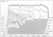
Various plots from the hifisound.de site for the Mini-Monitor Basic Mk2. Box construction, Crossover Diagram, Distortion, Frequency Response, Impedance, Waterfall. https://www.hifisound.de/en/Do-it-y...MK2-Speaker-KIT-without-Cabinet-Standard.html


Attachments
Frequency response and impedance plots from the Visaton Technical Datasheets and the frd and zma files extracted via FPGraphTracer.


Attachments
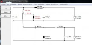
Resulting crossover frequency and impedance plots from XSim using the developed frd and zma files and the parts list from Hobby HiFi. Dxo file included. Differs greatly from previously posted plots from hifisound.de website, perhaps because these are from datasheets and those are measured results?

Attachments
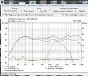
Directly comparing the only measured FRD for the finished speaker (from hifisound.de) to the Xsim simulation above, above 1000Hz similar enough, I guess, but below 1000Hz, the Xsim simulation, as well as the woofer datasheet, show a dropping off of response. Perhaps the Xsim simulation fails to account for the vented output? Is Xsim output only good for sealed enclosures? And how does it account for the baffle? Seems like Xsim output might be fun to play with, but not very useful in real life as a simulator? Is the way to get around this to take actual measurements of the woofer in the box and use that for the frd file?
It is useful, but you need to use responses measured in your box, on your baffle. You may be able to simulate this (effect of box and baffle) with other software.but not very useful in real life as a simulator?
This issue can easily be demonstrated by comparing real world measurements with an Xsim model using the same crossover, but using manufacturer's data and traced FR and ZMA.
I've attached a comparison of Paul Carmody's renowned Classix II with my Xsim model; the Xsim is the top graph: very different!
I used Dayton's data for the woofer and fptrace to get the data for the tweeter.
Geoff
I've attached a comparison of Paul Carmody's renowned Classix II with my Xsim model; the Xsim is the top graph: very different!
I used Dayton's data for the woofer and fptrace to get the data for the tweeter.
Geoff
Attachments
So I will have to use something like WinISD to insert the effect of the box and port. I'll see how that compares to the measured response.
Measured the two woofers I have in hand with DATS and compared to the published impedance data, very good correlation between them all. The zma files from DATS, when inserted into XSim model using the frd and zma files from FPTrace, barely change the results.


Measured the two woofers I have in hand with DATS and compared to the published impedance data, very good correlation between them all. The zma files from DATS, when inserted into XSim model using the frd and zma files from FPTrace, barely change the results.
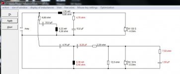
I found some good info on German sites regarding this speaker. Also discovered my crossover diagram in post #6 is incorrect, the inductors are swapped. The necessary crossover information is provided in an article from Hobby HiFi magazine dated 1/2014.


I had a look at your proposed project in Boxsim 1.2:
https://www.diyaudio.com/community/threads/boxsim-full-system-design-from-visaton-free.267787/page-2
It was quite easy to modify the default project in 1.2 to the W130S-4 and SC10N drivers. I also changed the reflex tuning frequency to 53Hz and the box to 15L.
Bass reflex tunings here:
https://www.visaton.de/en/products/drivers/bass-midranges/w-130-s-4-ohm
Results below. Along with some more complicated modifications which may or may not sound better.
Looks an OK speaker. The impedance correction is optional. You could try this in Boxsim 2.0 also.
Attachments

I appreciate the effort. Looks like I have new software to learn. I ordered the SC10Ns from Digikey, $20 each + shipping. I was surprised to see they charged the 10% tariff for China made products. Then I looked at the woofers and there is no indication anywhere of country of origin. Thought I was getting German product here. Quality control measures excellently on the woofs, the two drivers cannot be more identical.
Looks to be under $150 for all parts for this design, in the USA at least. One question, the 1.5mH can come in steel laminated (18awg .3ohm) or air core (19awg .75ohm) for the woofer, which would be preferred? The Hobby HiFi article has the laminated specified (at .3ohm).
https://www.madisoundspeakerstore.c...uctors/1.5-mh-steel-laminate-inductor-18-awg/
https://www.madisoundspeakerstore.com/air-core-19-awg/madisound-1.5-mh-19-awg-air-core-inductor/
My slightly dry humour and innate laziness suggested to me that it is surely far easier and quicker to use very competent Visaton's FRD and ZMA files and their own simulator rather than do it for yourself!
Ferrite and laminate core inductors are provably worse than air-cores due to hysteresis. Whether you can hear it, whether you get close to saturation, I don't know. The greater DC resistance of otherwise similar air cores is not necessarily problematic. The simulator allows for it. Noteable facts about coils are that inductance increases as the square of the number of turns, and that ferrite or laminate cores increase inductance about 4-fold.
My wise old friend sreten often pointed out that a loudspeaker magnet is itself a ferrite core at heart, so only 50% improvement is likely.
Money no object, I would use air-cores with thick wire guage. In the UK, a 1.5mH ferrite is about £8, a 1.5mH air core £13.
I lost some confidence in the Visaton datasheet for this driver when I noticed that on the very datasheet for it, the tabulated fs is 50hz, while the impedance graph provided on the same sheet clearly shows it as around 62 Hz. I measured 65 Hz with DATS. And very different T-S values between BoxSim software values and DATS:
Qes .55 .6967
Qms 2.54 4.046
Vas 15 6.23
Le .1034 .4708
I will email Visatron for an explanation, but I think I am going to go with the measured values for now for modeling. Perhaps measuring the driver for frd myself also to see how that compares. I plan on building the speaker to the Hobby HiFi crossover values at some point and comparing to the simulated values. It looks like Hobby HiFi sends out an air core inductor with the kit.
Attachments
Last edited:
With respect, I think it is hardly worth worrying about! I'd be surprised if Visaton even reply....
Don't bass speakers break in with time and change values?
The 5" W130S is more of a closed box driver in reality, but I am sure reflex will add something. I would guess 10 to 15L might be reasonable, and a 2" wide tube with a 3" length will be in the right ballpark.
I have reason to think Visaton have remeasured most of the driver files for Boxsim 2.0, but that is for you to ascertain.
Cone breakup around 7kHz and that 1.3kHz peak would be my main concerns. But it is a better design than most commercial designs which would doubtless use a simpler crossover.
Very good. Out of interest, what did you decide for the crossover? Easy enough to snapshot a smallish image and upload it.
So many ways to do crossovers... I never know which sound best really! But always have to fiddle around to get tweeter level right for my room.
Best Regards from Steve in Portsmouth UK.
🙂
So many ways to do crossovers... I never know which sound best really! But always have to fiddle around to get tweeter level right for my room.
Best Regards from Steve in Portsmouth UK.
🙂
- Home
- Loudspeakers
- Multi-Way
- Visaton W130S-4 + SC10N-8