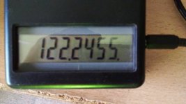
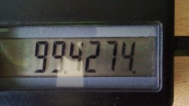
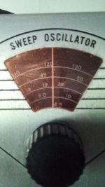
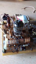
I restarted my old project of a FM tuner using tubes and permeabilty tuner, I already talk about it some years ago here. Here is the first step, the local oscillator running 12MHz above the incoming signal, such is the FI value choosen because of better image rejection. Also the frequency meter is displayed.
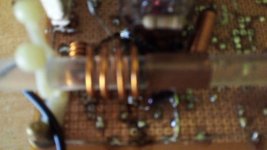
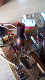
The tunning device is very crude still, but I am satisfied. A rod of acrylic material of about 9mm external diameter over which a short piece of copper tubing is provided. Over the copper tubing, a thin layer of electroltic copper was deposited using copper sulphate and an electrolytic solution, for reduce the superficial resistance and increase the Q of the tunning device, in fact oscillator's grid bias decrease less than a volt from one end to other of the oscillating range.
The tube shown is a ECF801.
Next steep is more difficult, the ECC88 cascode RF amplifier.
I shall keep posting.
Attachments

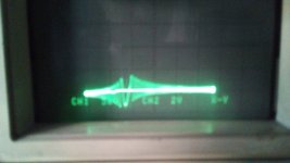
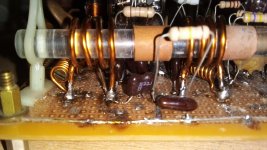
Here more pics showing the oscillator beating with the sweep generator signal to check tje cleaness of the signal generated, and a more expanded pic of the layout. The coil still unused will be the RF amplifier anode load.
Attachments


Wow what a great project Osvaldo, I will follow with a lot of interest.
Pedazo de projecti Osvaldo, lo seguiré con mucho interés.
Pedazo de projecti Osvaldo, lo seguiré con mucho interés.
Congratulations Osvaldo -- many web pages discuss the mechanics of the Collins PTO -- used in the R390 receiver.
Thank to all folks for your good wishes. I forgot to say that the resistor shown is a 12K anode dropping and the anode voltage is close to 60V. The frequency drops some KHz during warm up, but once stabilized thermically, seems very stable. Listening the carrier in my FT 7800 sounds clear.
To be continued.
To be continued.
I am thinking the reverse of this which is transistor front end and 1st IF , Tube IF 2nd and tube detector then IC stereo demodulation.
My project includes tubes at all stages including the rectifier and voltage regulator for LO and AFT devices.
Hats off to you, Osvaldo!
Inductance tuning has been done several times even in consumer radios. Especially German manufaturer SABA is known for it in their table radios.
There is something that I don't understand, though. Why did you pay special attention to have the tuning cores as conductive as possible? In my humble understanding this would result in an effective short turn when pushed into the inductor, hence decreasing Q instead of increasing it? SABA used conical aluminium cores in their units, whose conductance maginally is inferior to that of copper. And what's the advantage of 12 MHz IF instead of the usual 10.7 MHz which would have allowed you to use stock IF transformers?
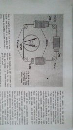
Here's the schematics of a FM unit using a E88CC in cascode as frontend.
Best regards!
Inductance tuning has been done several times even in consumer radios. Especially German manufaturer SABA is known for it in their table radios.
There is something that I don't understand, though. Why did you pay special attention to have the tuning cores as conductive as possible? In my humble understanding this would result in an effective short turn when pushed into the inductor, hence decreasing Q instead of increasing it? SABA used conical aluminium cores in their units, whose conductance maginally is inferior to that of copper. And what's the advantage of 12 MHz IF instead of the usual 10.7 MHz which would have allowed you to use stock IF transformers?
Here's the schematics of a FM unit using a E88CC in cascode as frontend.
Best regards!
Hello Guy and thanks for the comments. Let's see: copper cylynders were futherly "recoppered" using copper sulphate bath ( plus a small sulphiric acid) to increase superficial conductivity. Copper sulphate is cheap because it is used as insecticides in some instances. The high conductivity shorted turn inside a coil receives its variable AC flux creating a counter current in it because of eddy currents. This confines flux lines to the space between coil and slug, reducing consecuently, the inductance.
Similarly to a transformer, secondary resistance and inductance is transfered to the primary as the square of the turns ratio. Then if the slug has HIGH conductivity (as low resistance as is possible), then the Q is not materially affected as Q is (2 pi freq) inductance / resistance.
Also, being copper diamagnetic like aluminum and most non-magnetic meterials, there is a marginal effect of reject lines forces because of the reduced permeability at DC and low frequencies.
The range of variation on inductance is governed mainly in my case by a small inductance in series with the large tuning ones, also with a bronze screw inside them acting as "padder inductance" in place of the usual capacitance, but also by the coil diameter/ slug diameter. The former is a fine adjust and the latter a coarse one.
When boy there was a Philips table radio model BOAL47U using 4 tubes (UL81 +UCL82+UBC81+UCH81) that used permeabilty tuning, but at 1MHz any available powdered core does well its job.
Interesting issue, having used tuners with ECC85, ECC88 but with tuning caps, long ago (1960s). My preference remains mechanical tuning and I still have a nice collection that will be used some day. The 3-coil slug-tuned device I once used in an Elektor project. If memory serves well, made by Vogt. Silver plated tape for the windings, phenomenal Q.
Attachments
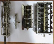
Precious pieces. Seems to be made of brass.
Mechanics is a bit complicated for me as I do not have presicion tools.
Mechanics is a bit complicated for me as I do not have presicion tools.
- Home
- Source & Line
- Analogue Source
- A new FM tuner with Compactron Tubes