I have the NAD Amp with the service manual attached. I'm hoping someone can help me diagnose a issue. The amp stopped working a while back. I finally got around to taking a look to see if I can find the issue.
Symptom:
Amp light would turn on, you'd hear two 'clicks' (relays) but nothing worked. No sound output no matter what input was selected.
Sorta cause:
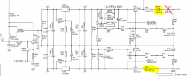
Resistor R46 (In attached capture document) was open. Looks like it got too hot. I ordered a replacement 51O 1Watt resistor and put it in today. Now I have sound, but the resistor is really really hot. Discoloration hot.
More fun:
Looking around I noticed that the resistor seems to have a voltage drop across it of 8Volts. If I did the math right (very likely I didn't) that comes out to about 1.25 Watts (1/4 watt above rating). Obviously, if that math is right, that wouldn't be good.
Looking around even more I noticed that D110 (also marked in attached capture) seems to also be running very hot. It is also rated at 1watt. It seems to also be dropping around 8V (just measuring voltage on one leg then the other and subtracting).
I'm thinking I didn't find the root cause of this issue, that is the blown resistor I found I'm thinking was just a symptom of some other issue. Further I think whatever issue is causing R46 to run hot, it also making D110 run hot. Anyone able to give me some suggestions? I check the other resistors in the area they all measure correctly. I'm an electonics newbie so I'm looking for some help. I'm thinking that whatever is bad must be impacting both devices? But I don't read the schematics well enough to be able to see something that would affect them both like that?
Any ideas?
ps. the amp is working, it discolored R46 and D110 but is working... Could the design just be poor and those components 'normally' run hot?
Thanks for any suggestions guys/gals!
- Craig
p.s.s. Diode D111 is crossed out as it isn't on the board. There is a place on the board for it and it is labled. But it just has a jumper wire across it.
Symptom:
Amp light would turn on, you'd hear two 'clicks' (relays) but nothing worked. No sound output no matter what input was selected.
Sorta cause:
Resistor R46 (In attached capture document) was open. Looks like it got too hot. I ordered a replacement 51O 1Watt resistor and put it in today. Now I have sound, but the resistor is really really hot. Discoloration hot.
More fun:
Looking around I noticed that the resistor seems to have a voltage drop across it of 8Volts. If I did the math right (very likely I didn't) that comes out to about 1.25 Watts (1/4 watt above rating). Obviously, if that math is right, that wouldn't be good.
Looking around even more I noticed that D110 (also marked in attached capture) seems to also be running very hot. It is also rated at 1watt. It seems to also be dropping around 8V (just measuring voltage on one leg then the other and subtracting).
I'm thinking I didn't find the root cause of this issue, that is the blown resistor I found I'm thinking was just a symptom of some other issue. Further I think whatever issue is causing R46 to run hot, it also making D110 run hot. Anyone able to give me some suggestions? I check the other resistors in the area they all measure correctly. I'm an electonics newbie so I'm looking for some help. I'm thinking that whatever is bad must be impacting both devices? But I don't read the schematics well enough to be able to see something that would affect them both like that?
Any ideas?
ps. the amp is working, it discolored R46 and D110 but is working... Could the design just be poor and those components 'normally' run hot?
Thanks for any suggestions guys/gals!
- Craig
p.s.s. Diode D111 is crossed out as it isn't on the board. There is a place on the board for it and it is labled. But it just has a jumper wire across it.
Attachments
You need to recheck the voltage across the resistor. 8 volts would be a power dissipation of just 0.125 watts. W= V squared/R so that is (8*8)/510 = 0.125
That wouldn't discolour a 1 watt part.
D110 is in the positive supply and so pretty much unrelated to whats going on with R46. The heat in the diode sounds as if it will be normal tbh. Remember that many semiconductors are quite happy at junction temperatures in excess of 100C.
Are the -26 and +26 volt values correct.
Scrub that... I took the value from your text (510) and not the diagram 51.
So 1.25 watts. Manufacturers do do this very often, something I've seen countless times in TV's and so on over the years. I'd bet its normal and the part is under rated.
So 1.25 watts. Manufacturers do do this very often, something I've seen countless times in TV's and so on over the years. I'd bet its normal and the part is under rated.
What model of NAD amplifier is it?
The circuit you attach is only the PSU
Upload the rest, maybe help.
The problem seems to come from the output stage, probably a faulty transistor causes a very high consumption and the PSU fails.
Do not continue testing without a power supply with lamps in series, you run the risk of ending up causing more damage.
Poor translation, I mean to power the amplifier with AC, but with a "protector" (very common in repairs) with lamps in series, if the output transistors are defective, consume more current than necessary, the lamps will turn on in that case , I do not know how many watts you need for 110 volts, (quantity of incandescent lamps, it's a problem in LED days, they still get here) but someone from your country can tell you that, otherwise you can build it according to the maximum consumption indicated on the back of the amplifier.
Last edited:
Poor translation, I mean to power the amplifier with AC normally, but with a "protector" (very common in repairs) with lamps in series, if the output transistors are defective, consume more current than necessary, the lamps will turn on in that case , I do not know how many watts you need for 110 volts, (quantity of incandescent lamps, it's a problem in LED days, they still get here) but someone from your country can tell you that, otherwise you can build it according to the maximum consumption indicated on the back of the amplifier.
I think the power supply as posted is just showing the low voltage and low current stabilised rails that will be used for the preamp sections.
Power Supply United for preamplifier +26 volts and - 26 volts
for amplifier + 55 volts and - 55 volts ( look to the right ) 😉
for amplifier + 55 volts and - 55 volts ( look to the right ) 😉
Thanks for the help! Yes, all the places where I check labeled +26 or -26 are very close to correct (25 + change).
Yes, sorry the 510 was supposed to be 51o (ohms.)
Yes, sorry the 510 was supposed to be 51o (ohms.)
You need to recheck the voltage across the resistor. 8 volts would be a power dissipation of just 0.125 watts. W= V squared/R so that is (8*8)/510 = 0.125
That wouldn't discolour a 1 watt part.
D110 is in the positive supply and so pretty much unrelated to whats going on with R46. The heat in the diode sounds as if it will be normal tbh. Remember that many semiconductors are quite happy at junction temperatures in excess of 100C.
Are the -26 and +26 volt values correct.
What model of NAD amplifier is it?
The circuit you attach is only the PSU
Upload the rest, maybe help.
The problem seems to come from the output stage, probably a faulty transistor causes a very high consumption and the PSU fails.
Do not continue testing without a power supply with lamps in series, you run the risk of ending up causing more damage.
Poor translation, I mean to power the amplifier with AC, but with a "protector" (very common in repairs) with lamps in series, if the output transistors are defective, consume more current than necessary, the lamps will turn on in that case , I do not know how many watts you need for 110 volts, (quantity of incandescent lamps, it's a problem in LED days, they still get here) but someone from your country can tell you that, otherwise you can build it according to the maximum consumption indicated on the back of the amplifier.
I'm trhing to upload the pdf for the entire manual but it is 2.5MB and won't let me upload it. I'll try to link to it:
http://www.bluefoxnet.com/files/c_356bee.pdf
Thanks for the help!
This resistor may be underrated so that it will blow and protect other things under a fault condition. You could space it from the board if it's causing discoloration.
I would check all rail voltages, check DC offset at the output, and if you can find the directions check the idle current for the outputs. Look for any electrolytics which look bulgy or have spilled their guts. If all that is OK, "leave it be" would be my advice.
Don't worry about using a dim bulb... If something was going to fry it would have by now.
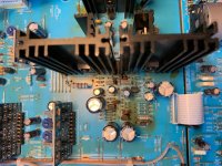
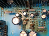
Thanks for all the help everyone! Hopefully we can zero in on some ideas. Attached are some photos of the AMP. Please note, resistor I replaced is discolored now (Colored lines are brownish), also note the board shows signs of heat by D110 which I did not replace. Again, everything is working. I just don't want to damage anything.
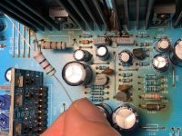
I'm holding another new resistor (I had to buy 50! LOL) to compare to one I replaced and is already discolored again.
I'm holding another new resistor (I had to buy 50! LOL) to compare to one I replaced and is already discolored again.
Attachments
Thanks for the thoughts! You've said a few things outside of my knowledge. But a few answers:
I checked all the voltages as marked on the circuit board. Things look good there (+/- 18, +/- 26, +/-55)
See the new photos I uploaded, if I understand you right the resistor does have a pretty big space from the board. I tried to make it about like the old one was.
I did visually inspect all the caps, things there look good. I also checked most, if not all, of the resistors (in the area) and they all seem right.
How do I check the 'rail voltages'? Happy to do that.
This resistor may be underrated so that it will blow and protect other things under a fault condition. You could space it from the board if it's causing discoloration.
I would check all rail voltages, check DC offset at the output, and if you can find the directions check the idle current for the outputs. Look for any electrolytics which look bulgy or have spilled their guts. If all that is OK, "leave it be" would be my advice.
Don't worry about using a dim bulb... If something was going to fry it would have by now.
Scrub that... I took the value from your text (510) and not the diagram 51.
So 1.25 watts. Manufacturers do do this very often, something I've seen countless times in TV's and so on over the years. I'd bet its normal and the part is under rated.
Thanks Mooly, if that is the case should I order a 2 watt resistor ( or 50! Lol) to replace it with? Or leave the one in it?
I checked all the voltages as marked on the circuit board. Things look good there (+/- 18, +/- 26, +/-55)
...
How do I check the 'rail voltages'? Happy to do that.
That's what you did, so, full marks.
Are you sure the manual you uploaded is for the same amplifier, as the power supply voltages seem to be different from what's on your board?
That's what you did, so, full marks.
Are you sure the manual you uploaded is for the same amplifier, as the power supply voltages seem to be different from what's on your board?
Thanks for the reply. It is a C356BEE. Listed on outside of unit and screen printed on board. What voltages are you seeing that don't line up?
- Craig
Thanks for any suggestions guys/gals!
- Craig
p.s.s. Diode D111 is crossed out as it isn't on the board. There is a place on the board for it and it is labled. But it just has a jumper wire across it.
Nothing to be thankful for, happy if I can help!
D111 is not in the circuit because it was simply replaced by D110 of the double peak reverse voltage drop. It is a zener diode, replace it with one of exactly the same specifications. It is not a common diode.
And, I do not share the phrase of someone who said "it would have been fried", the lamps act as a resistance that absorbs the current in case of short circuit in the output stage ....
The resistance that overheats and becomes discolored is because of something!
The issue is to find what causes it to overheat, not change the same indefinitely, until finding a "miraculous".
Now, if you decide to follow advice like "I would leave it that way", the decision is yours.
Apologies as I had not fully reviewed this thread ... or found the right part of the circuit diagram which I've now found...
That resistor is marked as fusible which means it shouldn't be running at over 1W, it's meant to go open if that happens (as occurred)
The fact it burned a new resistor as well and it's dropping 1.25W at idle means something is drawing excessive current on that -26v supply, or possibly the -18v supply.
You'll need to work through a process of elimination to figure out what that is...
And, I do not share the phrase of someone who said "it would have been fried", the lamps act as a resistance that absorbs the current in case of short circuit in the output stage ....
Which has already been eliminated as the amp is working... So it seems unnecessary at this stage in the game, as the damage would have already been done. IMO [emoji6]
Which has already been eliminated as the amp is working... So it seems unnecessary at this stage in the game, as the damage would have already been done. IMO [emoji6]
Everything can happen, that it is working is not synonymous with everything being perfect. Have you seen that burn on the PCB where D110 goes?
As you say, "control CC at the exit", well, it's what you try to avoid when that happens.
But I understand that OP does not have the knowledge to make a series that for us is something so simple and can avoid so much damage!
I have had amplifiers with the lamp (2x100 watts) lighting the room, it is a very healthy habit!
Apologies as I had not fully reviewed this thread ... or found the right part of the circuit diagram which I've now found...
That resistor is marked as fusible which means it shouldn't be running at over 1W, it's meant to go open if that happens (as occurred)
The fact it burned a new resistor as well and it's dropping 1.25W at idle means something is drawing excessive current on that -26v supply, or possibly the -18v supply.
You'll need to work through a process of elimination to figure out what that is...
What does 'at idle' mean? I wonder if I was checking it properly.
- Home
- Amplifiers
- Solid State
- NAD Amp Repair (Newbie)