Hi, I'm having some trouble bringing my F3 to life and could use some troubleshooting suggestions. You'll probably need an annotated schematic to follow, unfortunately. Working with just the right (red) channel (the left/black channel test points were even worse and the power resistors on that side were getting terribly hot so I unplugged just that side), I can measure 41V on the nose at the cap mx test point (TP2), suggesting both the PS and the first part of the circuit are okay. However, at TP1 (the Aleph CCS) I could measure only 17.6V and it would not change with any amount of fiddling of P2 or P1. Later I was able to adjust TP3 (source of the LU1014D) from 1.3V to 1.1V with the R5 power pot, at that point TP1 dropped to 11.6V and stayed, not changing with additional fiddling of P1 and P2. TP5 is at 5.7V and hasn't changed under these conditions of fiddling; TP4 is at 1.1V and similarly hasn't changed. During this testing, the LU1014D was as hot as 41c and dropped to around 35c after I lowered TP3; Q2 was 50c and about 45c after the TP3 drop; Q3 and 5 were about 33c throughout.
I'm using Chas Sample's block of output coupling capacitors, and during this test I had actual speakers hooked up to the outputs. Should I disconnect the speakers? Disconnect the output capacitors? Any help appreciated!
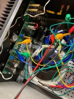
(Pic of the amp is attached in case it's of use)

I'm using Chas Sample's block of output coupling capacitors, and during this test I had actual speakers hooked up to the outputs. Should I disconnect the speakers? Disconnect the output capacitors? Any help appreciated!
(Pic of the amp is attached in case it's of use)
Hi ZM, the LUs came from Papa's stash by way of the most recent group buy, they're legit but I can't guarantee I didn't fry them (again!) trying to solder them. I honestly think I did a good job this time. The schematic I'm following is attached. Will try again to measure the test points tomorrow without speakers or inputs.leave speakers out of game while you're working
origin of your LU?
give us exact schmtc, nomenclature is important, so we can be on same page
Also, I do not have the LED shown below in circuit currently as the face plate of my case does not have holes to accomodate them, so I didn't wire them in. Please do not tell me they are an important part of the circuit!!
I had similar strange behavior when I cooked one of the LU's soldering it in place as I was learning SMD soldering on the first set of test boards. What type of solder did you use? I had better luck when I used 138 degree C solder paste for the LU. Schematic with Test Points labeled for reference (from Group Buy Thread).

I had similar strange behavior when I cooked one of the LU's soldering it in place as I was learning SMD soldering on the first set of test boards. What type of solder did you use? I had better luck when I used 138 degree C solder paste for the LU. Schematic with Test Points labeled for reference (from Group Buy Thread).
Oh man. I used Sn63/Pb37 ChipQuick solder, which comes with a little chart suggesting a peak temperature (I assume the melting point) of 235 degrees C. To solder I used a hot air pencil set to an air temp of about 320 degree C, and was careful with it, because I simply couldn't get the solder to melt at lower temps. Since I was adding the LUs last to the PCBs directly after abandonding the adapter board approach, I didn't have a choice about using a reflow oven to solder them first under more controlled conditions. Dammit. Is there an on-board check I can do to see if the LUs are okay?
Did you do these tests with the input grounded?
No. I had a source hooked up but got no changes in these values when I adjusted the volume of the passive preamp or switched the source out of circuit. Should I have grounded the input?
You could replicate this test circuit from the Zen V9 article by grounding the LU's gate and supplying +3V to the LU's drain (in circuit, with the amp switched off of course). View attachment 1012312
This was a good suggestion, thank you. With 3.1V applied externally, both LU's have a Vgs of 1.18V while drawing 1.17A, so by this in situ test, they seem to be fine?
Attachments
If your pre has DC on the output it might produce these results. Always better to reduce the number of variables in play.
Okay, thank you. Can you clarify, should the input be shorted across itself or grounded, e.g positive side to circuit ground? I'm not sure they're the same thing here.
Well, I can measure 26 Ohms between the negative line in and the ground test point, which has me concerned, but I don't know what to do about it. At any rate, I can't get the CCS above 13.4V. I've tried a bench supply vs the linear PSU, I've unhooked the speakers, and I tried unhooking the output caps. I'm using a different model of 5k Bourns pot (3266P-1-502LF vs. csample's spec for a 3296P-1-502LF) but the only difference I can find between them is in the # of turns, not the pin-out. Q4 (ZTX450) looks correctly oriented too. I'm at a loss.
Ignore TP3 for a moment. With your R5 power pot can you then adjust TP1 to be 20.5V?
If I crank the power pot so the wiper is shorted, I can get close to 3.12V (spec 3.5V typical) on the drain of the LU1014D, TP5 can get 7.7V (spec 8V), and TP3 gets 1.36V. Unfortunately the LU1014D was 64 degrees and may have been rising, and the CCS (TP1) never got above 16V.
How does you line in connect to the ground? On the PSU board? What then connects between the PSU board and your grand test point? (In other words, find out where that 26 ohms is.)
The earth ground on the line in connects to the PSU board ground, and from there to a star ground on the chassis. The PSU connects to the F3 board by positive and negative, though originally I also connected the F3 board ground to the star ground. I'll look into the places where the 26 Ohms appears.
Changing the subject a bit. I was curious about the voltages downstream of the cap mx, TP2, where I can read the near-spec 42V. The 100R resistor R21 drops it to 41.27V, the 1.5K resistors R17 and R16 drop it to 29.48V and 17.6V respectively, but the gate stopper R15 on Q3 of 221R, doesn't drop it at all- the gate of Q3 is also at 17.6V. Out of curiosity I measured across the other 221R gate stopper on Q5, R15, and it too doesn't drop any voltage- it's 46.6V on either side. Forgive me if this is a dumb question, but is this because there's effectively no current flowing through these gates? Otherwise I'd expect a voltage drop at this current of about 1.5V across each one? These resistors are Dales with the code "2210F" and I swear I measured them before I put them in.
You sure it's not the other way around? Shorting the resistance of the power pot should lower TP1, not raise it.If I crank the power pot so the wiper is shorted, I can get close to 3.12V (spec 3.5V typical) on the drain of the LU1014D, TP5 can get 7.7V (spec 8V), and TP3 gets 1.36V. Unfortunately the LU1014D was 64 degrees and may have been rising, and the CCS (TP1) never got above 16V.
If the wiper is all the way around to max resistance, then you may need larger values in R3 or R4.
From your picture in post 1,021 it looks like your negative line in is wired directly to the input on the amp board - from there it is a direct run through the ground plane of the amp board to the ground test point. If you are reading 26 ohms here maybe there is a loose connection in your input connector? Regarding the connection to the star ground, the mounting holes of the amp boards do not connect to the ground plane in the board. You shouldn't need to run any ground lines in addition to those you already have from the power supply and the input ground.The earth ground on the line in connects to the PSU board ground, and from there to a star ground on the chassis. The PSU connects to the F3 board by positive and negative, though originally I also connected the F3 board ground to the star ground. I'll look into the places where the 26 Ohms appears.
- Home
- Amplifiers
- Pass Labs
- F3 Builders Thread