Hi all. Im working on b&k m200 recaping and just general clean up and im wondering about the .47ohm 5 watt sand cast resistors that are on the output of the mosfets to the postive and negative rails going to the speaker outputs. I believe the resistors pretty much determine the total output of the mosfet/amp and they are a 10% sandcast resistors. I was wondering if switching these out with a mills kpa wire wound non inductive type of tge same 5watt .47 would yeld any sonic improvements. I know tube amp guys are always trying verious types. Maybe nelson pass could answer this cause it kinda falls inline with the zen mosfet amp correct.
Attachments
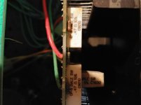

The original 0.47 ohm resistors are marked with a 10% tolerance - so they should be within 0.423 ohms to 0.517 ohms.
So what you measure at 0.6 to 0.65 ohms is way out of spec and will most likely mean the amp is also not biased to original manufacturer specs.
I would replace them with a higher spec resistor like the Panasonic or KOA Speer metal oxide types, 3 watt should be OK.
Fortunately, 0.47 ohms is a standard value (0.5 ohms can also be used here)
Ive had the amps a few years and iv always had the bias set to the factory 250ma. The dc output always stays around 5-6 mv because its servo controlled. Do you think whoever had them before i did didnt check the bias ever abd just let them get fried. I have 2 m200 and one ex442. Im guessing its more age then anything. But im proly wrong lol. I checked them with a fluke 115 rms meter
So what you measure at 0.6 to 0.65 ohms is way out of spec and will most likely mean the amp is also not biased to original manufacturer specs.
They might not be. On resistors that low in value the resistance of the test leads on the multimeter becomes a significant factor.
@ryan ... you need to set your meter on it's lowest ohms scale and short your test leads together, tip to tip. I'm betting it reads something like 0.2 or 0.25 ohms. You need to subtract this from any reading you take under about 20 ohms.
Last edited:
Yep your correct it was .1 which would make it .5 or so which is pretty close to .47 lol thanks guys. I still wonderbwhat all the fuss is about the mills mra resistors and the like. I have used them in passive level crossovers and it made a slight difference over the chaep sand cast ones.
I still wonderbwhat all the fuss is about the mills mra resistors and the like.
Mostly it's perfectionism run amok. When you get into the 1% improvement for 500% the cost you really should rethink your approach.
Then there's the technicians rules:
1) If it ain't broke, don't fix it.
2) If it is broke, know when to stop fixing it.

For one thing look up the spes on the parts is a big help.Toshiba T j115 and T K405. How do you tell the pnp vs npn
EIAJ standards, "2SJ" are for P channel and "2SK" are for N channel
Yep your correct it was .1 which would make it .5 or so which is pretty close to .47 lol thanks guys. I still wonderbwhat all the fuss is about the mills mra resistors and the like. I have used them in passive level crossovers and it made a slight difference over the chaep sand cast ones.
Any difference would be due to inductance, but sub-ohm wirewound's don't have many turns and aren't very inductive. A 1k wirewound is a different matter, hundreds of turns and there is significant inductance to the standard wound ones.
Incidentally to measure low resistances accurately you need a 4-terminal measurement (aka Kelvin measurement), which takes two multimeters and a current source, or a bench supply and multimeter, or a 4-terminal bench multimeter. My multimeter varies by 0.3 ohms or so by itself.
For one thing look up the spes on the parts is a big help.
EIAJ standards, "2SJ" are for P channel and "2SK" are for N channel
Sorry im just getting into this sorry i didnt think to look it up.
Incidentally to measure low resistances accurately you need a 4-terminal measurement (aka Kelvin measurement), which takes two multimeters and a current source, or a bench supply and multimeter, or a 4-terminal bench multimeter. My multimeter varies by 0.3 ohms or so by itself.
But i hardly think such precise measurements are needed for a service test. In a lab, developing measuring instruments, yes. In the current limiters for a working audio amp... naaaaa.
My portable meter can be off 0.2 or so depending on the battery state and so far, knowing that and compensating for it has been more than good enough. Just short the leads together and take note of the reading before you start measuring...
Sorry im just getting into this sorry i didnt think to look it up.
Spec sheets are our friends Ryan.
Also... take a look at the link in my signature line.
The purpose of these resistors is thermal stability and balancing the load between transistors. What maters is the matching between resistors and not the precise value. Assuming the resistors were made be the same vendor at the same time then they are probably nearly identical.
The inductance of such resistors is very small and not an issue at audio frequencies. In fact, a bit of inductance will reduce the distortion produced but the transistors during the AB cross-over.
Old amplifiers can be improved by applying advancements in circuit topology but other than replacing aging electrolytic capacitors, replacing other components is rarely useful. And beware if the placebo effect. If you modify an amp and manage not to mess it up badly, it will always "sound better".
- Status
- This old topic is closed. If you want to reopen this topic, contact a moderator using the "Report Post" button.
- Home
- Amplifiers
- Solid State
- Mosfet output loading resistors.