I'm sure you will get varied opinions, but here is what I did, as documented in the giant thread 'Terry Cain's BIB', post #5686:
-------------
The bottom is removable, allowing easy access should I need to make any adjustment to the damping. The front side of the slant board is covered from bottom to within 10” from the top with 0.5” Sonic Barrier damping (Parts Express #260-520). The bottom has one layer of 0.5” foam adhered to the panel plus a piece of 1.5” egg crate foam (PE # 260-510).
Roughly what Jim says. My default for the BIB is the front of the sloping internal baffle, one sidewall of the front section to a few inches below the driver, and a nice layer on the internal base.
If you want to experiment:
-Wrap a layer of material around the terminus from the top to about 6in down.
-Hang a long triangular strip of material from the terminus down to the bottom.
If you want to experiment:
-Wrap a layer of material around the terminus from the top to about 6in down.
-Hang a long triangular strip of material from the terminus down to the bottom.
Thanks all. Just what I wanted. I'm also toying with the idea of an iBiB, so I can play with the room gain influence. If I do I oimagine the driver position will change from Zillas V2 spreadsheet, How do I determine this Scootmoose I see you've had some experience with the iBib. Cheers
\ I'm also toying with the idea of an iBiB, so I can play with the room gain influence.\
The iBIB only moves the room gain/horn finish from the ceiling to the floor (larger due to its shortness — it could also be hung upside down from the ceiling.
The “karlson vent” is intended to spread out the pipe resonances a bit more (lots of room for experimenting there), making it easier to rduce the inherent ripple in a BIB.
Use of an upside down orientation of any BIB will be useful only if one of the 2 ideal driver placement Zd allow for a useful driver height when listening.
dave
Use of an upside down orientation of any BIB will be useful only if one of the 2 ideal driver placement Zd allow for a useful driver height when listening.
dave
Thanks Dave how do I calculate Zd? I'm given one by the Zillas V2 spreadsheet, which i can see from examining the cell?
Zd = 0.217 Lp or 0.416 Lp for the shorter inverted type. Those are the stock.
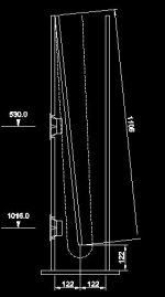
Thanks. So given the Bib calcs in my case, If I were to invert it, then I would merely opt for the 0.416 option (1016mm on the drawing)? Altering the base for a "lid"
Attachments
Last edited:
Right.
Thanks again Scott, forgive the ignorance, and the curiousity, but where/how was the 0.416 factor deduced? Thanks
The “karlson vent” is intended to spread out the pipe resonances a bit more (lots of room for experimenting there), making it easier to reduce the inherent ripple in a BIB.
dave
Thanks Dave, intrigued with the Karlson Vent, how do I go about calculated the size/curves? Thanks
Taper ratio and resonant profile.
Re the Karlson / Fulmer vent -guesswork, unless you model it in appropriate software (ideal is finite element) and empirically adjust to achieve what you regard as optimal results in a given application. There are no real formulas that I am aware of for sizing them.
Re the Karlson / Fulmer vent -guesswork, unless you model it in appropriate software (ideal is finite element) and empirically adjust to achieve what you regard as optimal results in a given application. There are no real formulas that I am aware of for sizing them.
Never seen any published tech info, but it's exponential, so easy to calculate. I published an Excel SS on the original 'FR' forum back when I still didn't know how to ~properly explain a lot of technical info worth a toot plus was planning on going back into the speaker building business, so wanted to protect my 'intellectual property' somewhat, which made the instructions a bit too cryptic, hence never used IIRC.
Regardless, once you know the BW desired [flare frequency], it's the same as designing an expo horn with an 1/8" dia. [IIRC] throat.
GM
Regardless, once you know the BW desired [flare frequency], it's the same as designing an expo horn with an 1/8" dia. [IIRC] throat.
GM
Never seen any published tech info, but it's exponential, so easy to calculate.
I knew that — thanx for poking my brain. I used that shape and then drilled holes into it to “open it out”. One has to experiment on how long to make it.
dave
Never seen any published tech info, but it's exponential, so easy to calculate. I published an Excel SS on the original 'FR' forum back when I still didn't know how to ~properly explain a lot of technical info worth a toot plus was planning on going back into the speaker building business, so wanted to protect my 'intellectual property' somewhat, which made the instructions a bit too cryptic, hence never used IIRC.
Regardless, once you know the BW desired [flare frequency], it's the same as designing an expo horn with an 1/8" dia. [IIRC] throat.
GM
Bingo. I've just been having a search of my HDD.
") Amazing what you find...
Amazing what you find...I published an Excel SS on the original 'FR' forum back when I still didn't know how to ~properly explain a lot of technical info worth a toot plus was planning on going back into the speaker building business, so wanted to protect my 'intellectual property' somewhat, which made the instructions a bit too cryptic, hence never used IIRC.
Regardless, once you know the BW desired [flare frequency], it's the same as designing an expo horn with an 1/8" dia. [IIRC] throat.
GM
Any chance of a calc for my bib tuned for an fs of 70hz, and what is the bw component? Cheers
Not anytime soon since all my Excel, MathCad, etc., calculators, tech library, etc., has been locked up in two damaged HDDs for many years now and don't have Excel to run them.
Bandwidth [BW] is a function of the speaker's upper mass corner frequency [Fhm] where it rolls off from its acceleration to mass controlled BW where T/S theory peters out:
Fhm = 2*Fs/Qts'
Qts' = Qts + any added series resistance [Rs]: HiFi Loudspeaker Design
GM
Bandwidth [BW] is a function of the speaker's upper mass corner frequency [Fhm] where it rolls off from its acceleration to mass controlled BW where T/S theory peters out:
Fhm = 2*Fs/Qts'
Qts' = Qts + any added series resistance [Rs]: HiFi Loudspeaker Design
GM
- Status
- This old topic is closed. If you want to reopen this topic, contact a moderator using the "Report Post" button.
- Home
- Loudspeakers
- Full Range
- BiB Damping