I do not see in any of the sheets specific mention as to the amount of crossover distortion, in the cases of A/B types, which is virtually all of them. Everyone seems to assume since the THD+Dist is so low, the specific amount of crossover distortion must be so vanishingly low, it may be disregarded, except for those who demand Class A operation, of course.
Has anyone ever been able to view what it actually looks like?
Has anyone ever been able to view what it actually looks like?
Thank you, Mark. I found two DA screenshots of a power amplifier output. The crossover had to be blown up 60db to see it clearly . In order to see a modern opamp crossover, would the equipment need to be high end, or would the information the analyzer provides need to be interpreted?


Power Amplifiers - A "First Watt" ABX Test - Benchmark Media Systems
Power Amplifiers - A "First Watt" ABX Test - Benchmark Media Systems
There are two basic approaches to coaxing an amplifier into showing easily visible amounts of distortion:
1. Demand insanely high noise gain from the circuit to the point where feedback is much reduced and ultimately it essentially runs open loop. If needed, annoy the output stage with low-impedance loading on top of that. Samuel Groner's opamp measurements are a typical example (60 dB noise gain, separate 600 ohm load test), and even the datasheet specs of modern opamps are often obtained by extrapolating like that. The advantage to this approach is that, well, basically anyone can do it, even without necessarily having to use particularly high-end equipment. The downside is that these are not exactly realistic operating conditions.
2. Use a distortion magnifier circuit of some sort to cancel out the stimulus signal. Published examples exist since about the early '80s, they have also been discussed elsewhere on this very forum. If the signal generator used is extremely clean, a pure notch filter for the fundamental may do. This allows researching amplifier performance in its natural habitat, if at the cost of dedicated circuitry being required (and a an increased risk of contracting ground loops).
I suggest researching both.
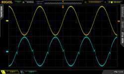
Here is an opamp (LM358) connected as an inverting amplifier with gain of -1.00. The input signal in yellow is a 5 kHz sine wave. The output signal is in blue, with crossover distortion clearly visible.
Studying the LM358 circuit schematic, you can see there is a "deadband" in the output stage which is (3 x VBE) wide, leading to relatively severe crossover distortion.
_
Studying the LM358 circuit schematic, you can see there is a "deadband" in the output stage which is (3 x VBE) wide, leading to relatively severe crossover distortion.
_
Attachments
The LM358 is, note, in no sense an audio opamp, as its full power bandwidth is only about 10kHz, slew-rate about 0.5V/µs, never mind the strange output stage, and its got high voltage noise. Its main claim-to-fame is very low power consumption and the inputs work down to the -ve rail.
You can fix the cross-over issue by adding a current-sink to the negative rail on the output to keep the darlington output in class-A, but there are many better opamps not requiring such a crutch.
You can fix the cross-over issue by adding a current-sink to the negative rail on the output to keep the darlington output in class-A, but there are many better opamps not requiring such a crutch.
Thanks for that. I doubt I will ever be able to notice that myself in this lifetime. I do see that over time, the manufacturers have been busy improving noise and performance.....Studying the LM358 circuit schematic, you can see there is a "deadband" in the output stage which is (3 x VBE) wide, leading to relatively severe crossover distortion.
_
The idea of Feed-Forward (in lieu of feedback) in the article was interesting. For the power amp, I like the LME49810, which I understand operates in Class A until a certain point of power output. Fine for me, and apparently for most ears.
Thank you everyone for your comments.
> "deadband" in the output stage which is (3 x VBE) wide,
> I doubt I will ever be able to notice that myself in this lifetime.
Even to an un-critical ear, this opamp family driving 600r sounds bad. I had not expected that, it was an hour to show-time, I had to cram the datasheet and realize that loading it into class A was the only way to do the show tolerably well.
The LM324/358 family is *automotive* market, really for sensors, where ground-referenced inputs, to-ground output, and low supply current may make the sale. A fuel-gauge, ABS, or dead-lamp indicator does not care about slew or crossover.
Making a very good AB stage is simple (no matter how many designs get it wrong). Basic concept must be over 50 years old by now.
> I doubt I will ever be able to notice that myself in this lifetime.
Thank you for chiming. I should have been more specific, in that I meant noticing the deadband in the schematic. Same goes for the gyrators in the stomp box thread, which I never heard of until then. I am more of an industrial systems designer, by experience and desire. However, there have been too many times when I have been bitten due to a combination of ignorance and laziness.
I have the bad habit of conceptualizing, then designing and building something, only to be shocked it doesn't work as intended, or at all!!
At that point, I start digging down deep, sometimes finding the whole thing has to be redesigned or trashed altogether. Lately, I have been better at designing in the head before creating a prototype.
Nicola Tesla did this routinely. After identifying the basic problem and conceptualizing a possible solution, he would build whatever it was in his head first, and by doing so, would realize the mistakes and avoid them, or redesign before building. He also lacked the inexpensive, off-the-shelf parts we take for granted, which may be an enticement for laziness and blind trust in manufacturers' claims.
In the case of opamps, we have the "audio" opamp, whose specs are lower than what is possible. There are available some with almost unbelievable specs yet they are neither suitable nor cost-effective for audio. What drives me crazy, is the spec sheets, even by the same manufacturer, sometimes make it difficult to compare opamps; it's worse if we try to compare say TI with ADI.
I recall back in the 1980s (and probably still these days), the published specs on stereos could not be compared as well. They all claimed comparably low THD but only within a certain range. Apparently, this practice is geared for sales propaganda, and even if they were comparable, most people can't hear the differences anyway in the same price range. Even if I were a multi-billionaire, I would be hard-pressed to justify spending $2,200 on a power amp. Besides, the likelihood it would be stolen is increased exponentially.
You will build DIY power amps whose total cost (summation from t=0 to t=1year after "completion") will far exceed $2200. But you won't mind because (1) that's hobby expense, not "purchased equipment" expense; (2) it will be smeared, spread out over a long period of time, numerous $150 credit card purchases at Mouser, ModuShop, eBay, etc; (3) you'll eventually realize that you could build a second copy of the final working amp for less than $800.
Indubitably true. I have also gained a modest parts warehouse..... you'll eventually realize that you could build a second copy of the final working amp for less than $800.
> he would build whatever it was in his head first, and by doing so, would realize the mistakes and avoid them, or redesign before building.
Yes, that works too. For some people.
Give a man a fish, teach a man to fish....."Most" folks chatting on-line really don't want to learn to fish from a bent pin and twisted fiber. I say "try it" and few do.
Yes, that works too. For some people.
Give a man a fish, teach a man to fish....."Most" folks chatting on-line really don't want to learn to fish from a bent pin and twisted fiber. I say "try it" and few do.
Yeah, I am working on a timing chart for a PIC controlling a mechanical relay. I know a flyback diode is needed so it doesn't make noise or burn thing out. Scanning an application guide, there was a suggested mod of adding a zener back to back with a standard diode of about the same coil voltage which reduces the delay caused by the diode alone.
I never saw this, so now I have to visualize the reverse polarity voltage caused by the collapsing field and figure out why the zener is faced the way it is in the paper. I will have to draw arrows around the circuit to fully understand. Maybe even with both conventional and electron flow directions. If I don't do this, I will be little more than an electronics assembler; somewhat analogous to a "parts changer" auto mechanic.
I never saw this, so now I have to visualize the reverse polarity voltage caused by the collapsing field and figure out why the zener is faced the way it is in the paper. I will have to draw arrows around the circuit to fully understand. Maybe even with both conventional and electron flow directions. If I don't do this, I will be little more than an electronics assembler; somewhat analogous to a "parts changer" auto mechanic.
The LM324/358 family is *automotive* market, really for sensors, where ground-referenced inputs, to-ground output, and low supply current may make the sale.
And it does that very well, and cheaply, too.
Remember that the LM358 is a second generation amplifier designed for the hyper price-sensitive automotive market. The first generation device was the LM2900 "Norton Operational Amplifier", which had a unique internal design, allowing an IC chip with extremely small silicon area. Since die cost is proportional to (silicon area raised to the power ~ 1.5), smaller die means dramatically lower cost, means lower price to the customer (Ford, Chevrolet, Pontiac, etc), means enormous sales volume.
Unfortunately, the Norton Opamp was juuuuuust a little different, and fresh out of school engineers (who work for cheap) had a hard time designing with it. It's not exactly the same as the work they did last year in uni lab projects. Which is why National Semi was forced to put out 50 page application notes about the LM2900, containing a hundred different circuits pre-designed, debugged, and ready to copy.
Customers whined, and then eventually rebelled, saying this is not the opamp we are looking for. We accept the incredibly low cost (due to it NOT being a traditional opamp), but we demand a traditional opamp so our greenhorn designers will make fewer mistakes and won't have to learn something new.
Thus was born the LM358/LM324. Its genius was to drastically reduce the input stage gm, which drastically reduces the size of the compensation capacitor -- the single largest-area piece of the opamp die. They (designer Thom Frederiksen) cranked the power much lower too, in order to have an excuse for selling it at a higher price than the LM2900. Making the IPS and OPS work all the way down to the negative rail was a savvy choice; why he also included a (3 x VBE) deadband, is a complete mystery to me.
BTW if you can find a used copy of Thom Frederiksen's out-of-print book "Intuitive IC Opamps", buy it. You will thank me.
Attachments
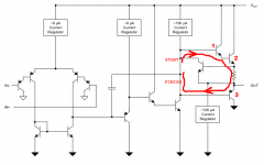
With an arrangement like this one, you will be able to magnify the Xover dist, whilst leaving it in its context.
https://www.diyaudio.com/forums/attachment.php?attachmentid=803403&d=1576775225
The effect is to exaggerate ~2000x the misbehavior of the AUT.
The other amplifier should be a good opamp; a NE5532 would be sufficient
If you use a LM358 as an AUT, you will need to reduce the ratio of resistors, to avoid saturating the output
Attachments
Last edited:
From what I've read he later came to regret this particular choice, too...Thus was born the LM358/LM324. Its genius was to drastically reduce the input stage gm, which drastically reduces the size of the compensation capacitor -- the single largest-area piece of the opamp die. They (designer Thom Frederiksen) cranked the power much lower too, in order to have an excuse for selling it at a higher price than the LM2900. Making the IPS and OPS work all the way down to the negative rail was a savvy choice; why he also included a (3 x VBE) deadband, is a complete mystery to me.
That makes me wonder, has anyone ever made something similar to an LM358 but with a non-broken output stage? There's the LMV358 but it's 5.5 V max only, or TSV358 up to 6 V. More promising: OPA2990 (2.7-40 V) or NCV952 (2.7-26 V), both RRIO, or TLV2170 (2.7-36 V, In to V-, RRO).
With an arrangement like this one, you will be able to magnify the Xover dist, whilst leaving it in its context.
https://www.diyaudio.com/forums/att...sover-distortion-visible-scope-xoveropamp-png
The effect is to exaggerate ~2000x the misbehavior of the AUT.
The other amplifier should be a good opamp; a NE5532 would be sufficient
If you use a LM358 as an AUT, you will need to reduce the ratio of resistors, to avoid saturating the output
The way this is usually done is to set up the DUT as for instance a gain of one inverting amplifier with 1k feedback and 1k series. Then you place a resistor of 1 ohm directly between the two opamp input pins. The opamp now has to provide extra gain to overcome this 'almost short' of 1 ohms against 1k, which is called noise gain (here 1000x or 60dB).
The advantage is that on the outside, levels do not change: 1V in gives 1V out. But all distortion products are amplified by the noise gain - 60dB here.
Jan
- Status
- This old topic is closed. If you want to reopen this topic, contact a moderator using the "Report Post" button.
- Home
- Source & Line
- Analog Line Level
- Opamp Crossover Distortion Visible on Scope?