A lot of good information from members here on modifying the 75. But how can I modify it for the least amount of money?
Would like to stay with 6550's unless there is a drastic difference in going to the KT120's.
Power supply caps its been said to increase the value by 3X. Seems logical. Coupling caps simply as a safety thing don't want new tubes being destroyed by some old caps.
The multi-cap also needs to be replaced again the age thing. How costly should one go when replacing it? Should one simply install a terminal strip near it and solder in some new caps and disconnect the original? Some of these multi-caps can cost $100 ea.
Bias diodes and bias caps. Is there really a need for ultra fast diodes here or will something cheap like 2) 1N4007's due? Caps something like 30/200vdc anything special needed?
Basically how cheap can I refit the amps and still have then sound good and be reliable?
The $100 can caps do not come with a service life rating. I've got a few 2010 or later CE's and FP's in my Hammond organ that work okay, but the 400 & 450 v Panasonic nichicon caps come with up to 5000 hour service life rating. I've put solder strips in my chassis, solder the radial lead caps to it. Be sure to use 600 v rated wire or higher to hook them up. Then I cut steel mesh to screw over the holes to let the heat out and keep the spiders on top.
Ultra fast diodes make more high frequency noise than standard grade. A sharp current edge has a higher high frequency content than a slanted edge. An annoying 120 hz buzz results unless snubbed out by RC networks.
However, 1n4007, while the die will hold off 800 v, the case will not. Air will short 1000 v per inch, the 1n4007 case is about 1/3 inch. I've found the best source of real inch long rectifier diodes is old TV's, CRT monitors etc. I've seen none for sale at distributors. You can probably buy anything you want in quantities of 100000 from On ST or diodesinc.
What Allen organ is this 75 out of?
Be sure to limit turn on surge with a NTCR in the AC line. Real rectifier tubes come on softly, whereas silicon rectifier diodes hammer the plates pretty hard from the instant you flip the switch. Some people don't believe in cathode stripping. For $2, a solder terminal strip and a NTCR, I prevent it even if it is a myth.
Last edited:
The $100 can caps do not come with a service life rating. I've got a few 2010 or later CE's and FP's in my Hammond organ that work okay, but the 400 & 450 v Panasonic nichicon caps come with up to 5000 hour service life rating. I've put solder strips in my chassis, solder the radial lead caps to it. Be sure to use 600 v rated wire or higher to hook them up. Then I cut steel mesh to screw over the holes to let the heat out and keep the spiders on top.
Ultra fast diodes make more high frequency noise than standard grade. A sharp current edge has a higher high frequency content than a slanted edge. An annoying 120 hz buzz results unless snubbed out by RC networks.
However, 1n4007, while the die will hold off 800 v, the case will not. Air will short 1000 v per inch, the 1n4007 case is about 1/3 inch. I've found the best source of real inch long rectifier diodes is old TV's, CRT monitors etc. I've seen none for sale at distributors. You can probably buy anything you want in quantities of 100000 from On ST or diodesinc.
What Allen organ is this 75 out of?
Be sure to limit turn on surge with a NTCR in the AC line. Real rectifier tubes come on softly, whereas silicon rectifier diodes hammer the plates pretty hard from the instant you flip the switch. Some people don't believe in cathode stripping. For $2, a solder terminal strip and a NTCR, I prevent it even if it is a myth.
Ok, talking about replacing the standard bias diodes with 1N4007's were looking at about 95vac on the bias winding and two diodes in series.
The rectifier diodes I will replace with the mouser part as suggested which is a bridge rated at 21A @1200 volts. The power supply caps upped to 680's@400vdc.
Cathode stripping? I simply don't believe in it with this amp. This amp was built in the late 50's? If cathode stripping had been a problem Allen surely would have made a modification. The guy I bought them from a retired organ repairman all his life laughed when I commented on SS rectification verses a tube rectifier and possible problems up the road. The guy commented that he had never seen one instance of cathode stripping on any Allen amp.
95 V rectification with 1n4007 is fine.
The ratings on semiconductors are done in dry nitrogen atmospheres if necessary. If the +- terminals on the bridge are 1/2" apart, at 400 v it should be okay even if you live on an island in the ocean. Residents of AZ & NM have less problems than coastal residents or the US Navy. I encountered a 1955 Wurlitzer organ here in the Ohio valley making farting noises occasionally in wet weather. The e-caps were 2008 so I proscribed a complete clean of the power amp, all B+ resistors, terminals tube sockets etc. Rather than do that, I found a donor wanting rid of a SS Allen 300. Anybody want an Wurlitzer 20W tube amp thats dusty?
Cathode stripping can be detected by plotting average service life of tubes of a given type in equipment with delayed B+ application versus a population of the same tubes that are hammered by SS diodes. If the repairman worked on allen amps, and his population did not include service hour recorders, he has no basis for an opinion. I don't either, but For $2 protection and using >$20 vacuum tubes which may go unavailable anytime, I'll install the B+ delay parts when not using a vacuum tube rectifier. I have new (2010) 5AR4 in my Hammond H100 organs. Two of them came with new output tubes, one of them with 100% original leaky e-caps. Sleazebag serviceman too lazy to change capacitors, the volume tripled with new ecaps. The old rectifier tube laying in there was fine with a stiff power supply.
Last edited:
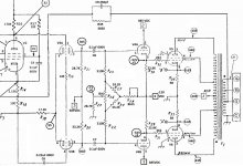
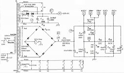
Can you link to a clear version of the schematic that shows the operating voltage and part values? My version is not very clear and it is difficult to identify the levels.
I suggest the 21A 1200V bridge is the wrong part to use. The diode current rating is far too high, and the voltage rating not high enough. I would strongly recommend 2x UF4007 in series for each arm of the diode bridge, and use diodes from the same batch and soldered close together so that they are at the same operating temperature. The aim is to use a diode with just enough current rating, and be fast.
Do you have sufficient test equipment to confirm the frequency response and stability of the amp is adequate, and the output stage is both dc balanced, and the ac is balanced sufficiently for low distortion?
These are courtesy of Brice. These are his revised schematics based on his modifications on his model 75's. They are found on the thread about Allen hum problem that I started.
My allen's have both inputs intact. One input uses the 12AY7 and the other input bypasses the 12AY7 still uses the gain control and the signal is directed to the Ef86.
My allen's have both inputs intact. One input uses the 12AY7 and the other input bypasses the 12AY7 still uses the gain control and the signal is directed to the Ef86.
Attachments
Last edited:
Can you link to a clear version of the schematic that shows the operating voltage and part values? My version is not very clear and it is difficult to identify the levels.
I suggest the 21A 1200V bridge is the wrong part to use. The diode current rating is far too high, and the voltage rating not high enough. I would strongly recommend 2x UF4007 in series for each arm of the diode bridge, and use diodes from the same batch and soldered close together so that they are at the same operating temperature. The aim is to use a diode with just enough current rating, and be fast.
Do you have sufficient test equipment to confirm the frequency response and stability of the amp is adequate, and the output stage is both dc balanced, and the ac is balanced sufficiently for low distortion?
The stock diodes in the power supply are rated at 600vdc@1amp.
The choke input configuration exhibits a turn-on surge PIV on the diodes. 1200V is a likely minimum PIV for each bridge 'arm'. Diodes in series should be derated. 2x 1kV diodes is appropriate when properly seriesed, and using UF4007 provides a good choice of fast diode for that application.
I'd suggest you would have to go through the detailed design of the circuit to estimate if any aspect of 'performance' may change, and also to determine what circuit changes are needed because of the change in part type. Some issues to sort through could include valve rp, grid voltage swing and effective capacitance and max leakage resistance, heater current, idle and peak current levels and B+ level and new power supply and OPT requirements (assuming you want to change idle and peak power targets).Would I see any increase in performance when using KT120's in place of KT88's or 6550's?
If you are unable to work through those technical issues then you could always try the change, and wait for something bad, or good, to happen - your call.
Would I see any increase in performance when using KT120's in place of KT88's or 6550's?
The heater power barely has enough current. I doubt you'll get more power but you might like the sound. I considered it but the amps were a friends.
Heater current for the model 75 seems to be adequate is it is rated for 5.5A and this provides current for 2) 6550's or KT88's @ 1.6A each for a total of 3.2A.
It provides current for 1) 6sn7 at 600mA, one EF86 at 200 mA and one 12AY7 at 300mA. Which is a total of 4.3A The other 6SN7 (V4) has its own 6.3 volt supply.
So we are looking at 4.3A of heater current. Now drop the 12Ay7 and we're sitting at 4A. Now substitute 2) KT120's in place of the 6550's or KT88's for an additional .3A each and we're up to 4.6Amps of heater current. Even with the 12Ay7 in circuit we are still under the rated 5.5A for that particular supply.
I think its safe.
I'd suggest you would have to go through the detailed design of the circuit to estimate if any aspect of 'performance' may change, and also to determine what circuit changes are needed because of the change in part type. Some issues to sort through could include valve rp, grid voltage swing and effective capacitance and max leakage resistance, heater current, idle and peak current levels and B+ level and new power supply and OPT requirements (assuming you want to change idle and peak power targets).
If you are unable to work through those technical issues then you could always try the change, and wait for something bad, or good, to happen - your call.
I toyed with the idea of changing to KT120's because another member an experienced member on the forum has gone over to the KT120's and seems to like their sonic characteristics over that of the KT88's or 6550's.
I'm on the fence. I seem to like the details of a 6550 over that of the KT88. In my mind the KT 88 seems to have a bit more punch at the expense of the fine detail.
Would an inrush limiter be a valuable addition? If so how does one calculate the size and does it need to be bypassed once the amp is stable up and running.
If memory is correct DJK used to use them in conjunction with a circuit that bypassed them once the amp was up and running say 15-20 seconds after turn on.
If memory is correct DJK used to use them in conjunction with a circuit that bypassed them once the amp was up and running say 15-20 seconds after turn on.
What one does is measure the steady state current the amp draws at significant wattage. A amp clamp meter is best for this but you can put smaller fuses in until you blow one. Then you look that the NTC inrush current limiter datasheet, for the resistance at 25% maximum rated current column. Pick a resistance that is negligible at that current rating.Would an inrush limiter be a valuable addition? If so how does one calculate the size and does it need to be bypassed once the amp is stable up and running.
If memory is correct DJK used to use them in conjunction with a circuit that bypassed them once the amp was up and running say 15-20 seconds after turn on.
For example a GE CL-60 has a maximum steady state current rating of 5 A. Your Allen 75 probably has a 3 amp slow blow fuse. So if current draw is 1 A @ 120 v most of the time, the CL-60 would drop 1.1 vac off the 120 vac most of the time.
If you are going to go to the trouble of putting a timer & relay in to short the resistor some time after turn on, no reason to use a NTC resistor. A wirewound resistor would work.
The choke input filter for B+ means there is no instantaneous inrush current to those filter caps. So the mains supply only immediately sees transformer primary and heater related inrush, with the B+ current ramping up over a few mains cycles.Would an inrush limiter be a valuable addition?
So compared to typical ss diode amps, your's is a little easier on in-rush. Hence adding an inrush limiter does not really appear to meet the 'valuable addition' criteria, when compared to a huge number of other amps that don't use inrush limiting.
Determining a suitable NTC, and then installing it so that it isn't a fire hazard, or causes other safety issues related to altering mains wiring and inserting parts in a mains circuit, should imho not be taken on lightly by diyers who are not adequately competent.
- Status
- This old topic is closed. If you want to reopen this topic, contact a moderator using the "Report Post" button.
- Home
- Amplifiers
- Tubes / Valves
- Allen model 75 modifications most bang for the buck.