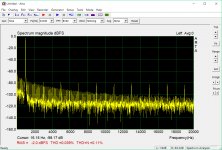
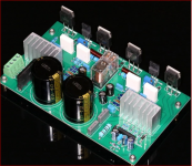
I just finished a UPC1342V + NJW0302G/NJW0281G stereo class AB power amplifier board from ebay. It's all in one board (power supply, speaker protection & amp). It was cheap so I decided to build it for my surround sound speakers. It works but FFT measurement (yellow graph) looks odd.
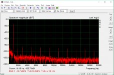
Is anyone familiar with the distortions shown between harmonics and what's causing it? My other amp from ebay (LJM L20SE kit, class AB) shown in red doesn't have it so I'm wondering. Thanks in advance.
Is anyone familiar with the distortions shown between harmonics and what's causing it? My other amp from ebay (LJM L20SE kit, class AB) shown in red doesn't have it so I'm wondering. Thanks in advance.
Attachments
I just finished a UPC1342V + NJW0302G/NJW0281G stereo class AB power amplifier board from ebay. It's all in one board (power supply, speaker protection & amp). It was cheap so I decided to build it for my surround sound speakers. It works but FFT measurement (yellow graph) looks odd.
Is anyone familiar with the distortions shown between harmonics and what's causing it? My other amp from ebay (LJM L20SE kit, class AB) shown in red doesn't have it so I'm wondering. Thanks in advance.
You, who on another thread, spend your time giving lessons endlessly to seasoned professionals in the most aggressive of ways, really, you do not know the source of odd harmonics in amplifiers ?
It is something teached in first year of any electronic schools.
You, who spend your time shouting that only the measures have a meaning in audio, you do not know how to interpret them and act accordingly ?
Fortunately, ridicule do not kill !
The solution is childish, and I would have helped you if my mother had not forbidden me to feed the trolls
Last edited:
Think its all power supply harmonics, multiples of 120Hz?I just finished a UPC1342V + NJW0302G/NJW0281G stereo class AB power amplifier board from ebay. It's all in one board (power supply, speaker protection & amp). It was cheap so I decided to build it for my surround sound speakers. It works but FFT measurement (yellow graph) looks odd.
Is anyone familiar with the distortions shown between harmonics and what's causing it?
My other amp from ebay (LJM L20SE kit, class AB) shown in red doesn't have it so I'm wondering. Thanks in advance.
I thought I was happy to be on your ignore list. I wonder how my post was visible to you. 😕 Also, you must not understand the phrase "distortions shown between harmonics"You, who on another thread, spend your time giving lessons endlessly to seasoned professionals in the most aggressive of ways, really, you do not know the source of odd harmonics in amplifiers ?
It is something teached in first year of any electronic schools.
You, who spend your time shouting that only the measures have a meaning in audio, you do not know how to interpret them and act accordingly ?
Fortunately, ridicule do not kill !
The solution is childish, and I would have helped you if my mother had not forbidden me to feed the trolls
The solution is childish, and I would have helped you
if my mother had not forbidden me to feed the trolls
Attachments
There are several kits meeting the description. One that I found may not be the same as yours but its clear that this one will have problems with rectifier harmonics anyway, as yours does, since the power supply and its switching AC currents are so close to the input stage in the uPC1342.
It's not a good design and probably was never measured critically for performance. The DIY market in China is intensely competitive and underhanded - so buyer beware.
It's not a good design and probably was never measured critically for performance. The DIY market in China is intensely competitive and underhanded - so buyer beware.
Attachments

Last edited:
I bought a cheap stereo chip amp from China, the bridge and smoothing caps were between the chips, moved them off board, vast improvement
Is anyone familiar with the distortions shown between harmonics and what's causing it? My other amp from ebay (LJM L20SE kit, class AB) shown in red doesn't have it so I'm wondering. Thanks in advance.
I keep asking myself the same question. That moiety shown in yellow is almost certainly an algorithmic freak. It should definitely not be there. Very confusing indeed.
Thanks for the technical input. It's the one on the right. It was very cheap and I bought it as an experiment.There are several kits meeting the description. One that I found may not be the same as yours but its clear that this one will have problems with rectifier harmonics anyway, as yours does, since the power supply and its switching AC currents are so close to the input stage in the uPC1342.
It's not a good design and probably was never measured critically for performance. The DIY market in China is intensely competitive and underhanded - so buyer beware.
I'd be interested to know whether you tested both channels and compared the levels of harmonics. From that, you could be more certain of the source and probably what could be done about it.
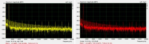
Thanks Evenharmonics. We could expect them to be different, due at the least to different layout of each channel. The proportions of noise to harmonics have also altered and harmonics are lower in the red graph. That much could be explained by PCB track location but the software identifies a strong proportion of sub-harmonics as noise when they are clearly artefacts of some distortion that I'm not familiar with. That may be related to the particular sound card. perhaps someone with the knowledge might care to enlighten us.
I suspect there is also a problem with the chip. The supplier may want to say they are original NEC uPC1342 ICs but I find it unconvincing that so many years after NEC cease manufacture, large quantities turn up in China and Indonesia in pristine, new condition and quickly find their way to many competing DIY kit suppliers. Large volumes are offered in capped monthly lots which should tell us they're in production.
I suspect there is also a problem with the chip. The supplier may want to say they are original NEC uPC1342 ICs but I find it unconvincing that so many years after NEC cease manufacture, large quantities turn up in China and Indonesia in pristine, new condition and quickly find their way to many competing DIY kit suppliers. Large volumes are offered in capped monthly lots which should tell us they're in production.
Thanks for your input. It's no big deal for me as it was just a cheap experiment. I've already installed a different amp board and it's been working fine.
There are several kits meeting the description. One that I found may not be the same as yours but its clear that this one will have problems with rectifier harmonics anyway, as yours does, since the power supply and its switching AC currents are so close to the input stage in the uPC1342.
It's not a good design and probably was never measured critically for performance. The DIY market in China is intensely competitive and underhanded - so buyer beware.
I wonder if that amplifier board could be salvaged by simply routing the transformer to an external rectifier and filter board first. Then the smoothed DC could be input into the "all in one" board. Perhaps the all in one board does not necessarily need to be modified? Would the rectifier harmonics problem be greatly improved if you just connected the smoothed DC from an external rectifier and filter board to the AC screw terminal inputs of the "all in one" board?
- Home
- Amplifiers
- Solid State
- Amp Kit from ebay