Hello Sir Mile, where i can find dc speaker protect with rellay for ax16?
Sent from my Coolpad 8297W using Tapatalk
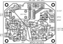
You can use DC555 protect.
Attachments
Last edited:

sir apex what is the minimum and maximum supply vcc vee to this A16? please
Minimum +/-30V maximum +/-60V. I suggest +/-45V. With +/-35V you can use BD139/140 instead 2SA1837/2SC4793.
Regards
Thank you so much.You can use DC555 protect.
Regards,
Kuntarman.
Sent from my Coolpad 8297W using Tapatalk
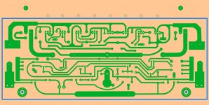
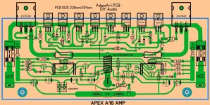
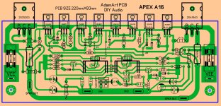
hi.. sir apex here is another one PCB size is 226mm by 91mm soon i will do work another version for thermally coupled as you mention BC546 thermally coupled
😕 not good, at all ,wrong layout my friend ,input, low signal ,near strong currents , from output ,not acceptably 😱
Attachments
Last edited:
😕 not good, at all ,wrong layout my friend ,input, low signal ,near strong currents , from output ,not acceptably 😱
I agree with you...
One more thing, 100uF (220 or 470 uF even) rail decouple could well be placed above the fuses where its more useful.
+ no need to give too much importance to curves/ symmetry/beautification😉...some curves are totally unnecessary like B of 2SC...
reg
Prasi
x, that's implied in Alexmm's post... get the o/p as far away as physically possible from i/p...like my layout of Ranchu/AKSA 'Very Simple Quasi Comp Amp' or Apex AX-14 some pages ago... You should build it, its the star amp of this thread/ start amp of this thread "Ultimate Fidelity"😉Also magnetic fields from inductor should be kept away from input stage.
Last edited:
I think since Alex MM circled the one trace going by output terminal it may get lost that what is ended is to move everything like input transistors and their traces far from high current output traces and the coil, which is a big electromagnet. Much worse than the single straight track of the output spade. Your board does indeed do a good job of keeping the high current section away from input section for how small it is.
I already built the Prasi layout - unless you are talking to Adamart.
I already built the Prasi layout - unless you are talking to Adamart.
I think since Alex MM circled the one trace going by output terminal it may get lost that what is ended is to move everything like input transistors and their traces far from high current output traces and the coil, which is a big electromagnet. Much worse than the single straight track of the output spade. Your board does indeed do a good job of keeping the high current section away from input section for how small it is.
ok... English is not a native language to many people here including me...but however, generally we understand whats intended to convey...
Prasi, its me😀...I already built the Prasi layout - unless you are talking to Adamart.
talking to to anyone who is prepared to heed to the advice.

hello alex MM thanks for the correction of PCB and to everyone thank you to see my error soon that will be corrected sorry for my error im still learning and student of electronics
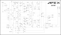
22k feedback resistor should be connected before inductor.
If possible remove inductor on your layout.
Attachments

simple solutions to complex problems, nice suggestion.22k feedback resistor should be connected before inductor.
If possible remove inductor on your layout.
I made FH12 mod.
The bias current might be slightly over compensated, but I trade it for simple construction.
This is the simulation file.
Bimo, do you have a PCB designed form FH12 mod?
Can you share?
Thanks
Bimo, do you have a PCB designed form FH12 mod?
Can you share?
Thanks
No, but my friend, Zaki (facebook's name) made it and he upload to facebook group that called "DIY Audio Indonesia".
Too bad, I'm not on facebook...No, but my friend, Zaki (facebook's name) made it and he upload to facebook group that called "DIY Audio Indonesia".
Any chance it can be copied to diyaudio?

- Home
- Amplifiers
- Solid State
- 100W Ultimate Fidelity Amplifier