This might seem like a weird question, given the expense of single-ended transformers versus that of pushpull. I understand that it doesn't work to use a PP OPT in a SE amp. However, I'm wondering if I can salvage two small matching single-ended OPTs from an old radio for a mono pushpull circuit by wiring them in series and adding the B+ to the middle of the two.
If this does work, do I assume that each SE OPT should be 1/2 the load of a suitable PP OPT? Thanks!
If this does work, do I assume that each SE OPT should be 1/2 the load of a suitable PP OPT? Thanks!
No, it does not seem weird, and such the topology does exist. I am planning to build a small amp like this in the near future. As the author of prototype said: I just wanted to utilize those cheapo SE transformers kicking around my desk...
The schematics consists of the phase-inverter stage driving the CCS-biased output stage, no FB. The only difference is that the secondaries go in parallel opposite-phased, hence the output impedance is halved, e.g. with two identical 10Wa small 5K:8E SE transformers you get it 4E with up to 20Wa per channel.
Gurus, please refer us to readings on this topology, how is it called btw?
The responses on such amp are very positive. Everyone notes the excellent microdynamics as the output stage still is... kinda SE.
Last edited:
In the end it won't be PP at all. Just a paralleled SE. Just because you tie the trannies together with a common B+ is not enough to call your circuit PP. All amps will have a common, filtered, B+ source. If you feed one tranny with a reversed signal you will have to swap the output leads to put it in phase with the other or you will have a neutral output. The offsetting idle current and neutral core flux of PP won't exist. Also, if you use an existing PP circuit it will be biased for cold AB operation and will not be putting out full SE power at higher signal input levels.
Last edited:
Of course it's push-pull. The two halves of the output stage are driven in opposite polarity and output signals in opposite polarity that are added algebraically. Even harmonics and power supply noise will cancel, etc.
Core magnetization will have the advantages and disadvantages of DC bias: small signal operating point moved away from the lower slope region near zero crossing at a cost of poorer coil geometry from larger size. The magnetization curve ("B/H curve") is a secondary, but not necessarily minor, factor in valve loading. Magnetization current appears as a parasitic in parallel with the reflected ideal transformer's load, so its import varies with the valves' anode resistance.
All good fortune,
Chris
Of course it's push-pull. The two halves of the output stage are driven in opposite polarity and output signals in opposite polarity that are added algebraically. Even harmonics and power supply noise will cancel, etc.
Core magnetization will have the advantages and disadvantages of DC bias: small signal operating point moved away from the lower slope region near zero crossing at a cost of poorer coil geometry from larger size. The magnetization curve ("B/H curve") is a secondary, but not necessarily minor, factor in valve loading. Magnetization current appears as a parasitic in parallel with the reflected ideal transformer's load, so its import varies with the valves' anode resistance.
All good fortune,
Chris
Two seperate SE trannies don't need a phase splitter/inverter, just one drive signal to both tubes and it will stay in class A. The direction of the current and signal through the primaries is irrelevant because the cores are seperate. Nothing mixes or cancels. You can wire the secondaries in series or parallel if you want to, with the propper phase, and then use the appropriate speaker load for for the way you do it. But in the end it is parallel SE. There is no PP, it's just push-push or pull-pull.
You can use 2 single ended air gapped transformers in a “push pull” amplifier. I will talk about what I consider to be the biggest single advantage of such an amplifier when you keep it in the class A operating region. Because of the topology and advantages, I will also limit this discussion to an amp that uses parallel crossed secondary connections (not series secondaries), triode output tubes, and no feedback.
The amplifier circuit is identical to a push pull amp, all the way to and including the output tubes.
But the 2 single ended air gapped transformers replace the push pull transformer.
Keeping the signal levels to the class A region:
The advantage of using a pair of SE air gapped transformers as output transformers
in a class A push pull amp is that there are no magnetic zero crossings in the transformers.
That keeps it out of the non-linear low, zero, and reversing polarity magnetic regions.
The quiescent current causes the magnetic flux to be part way up the BH curve, just like
in a single ended amplifier output stage.
1. Then limit the signal swing so the tube currents never cut off (causing zero flux, or in this topology, becomes class AB where it goes to magnetic reversal).
2. Then limit the signal swing so the tube currents do not go large enough for the transformer core to saturate.
1 and 2 above are just the rules we use to keep a single ended amplifier in its linear region.
Now we are in the more linear region of the BH curves.
Also, the "push pull" output topology causes 2nd harmonic distortion to be reduced.
It also causes the output impedance to more linear over the output swing (in the class A region) than a single ended amp.
It is that simple. By the way, you can disconnect the cross connected secondaries, and
test each stage (you have 2 single ended outputs that are phase reversed, but should test to be otherwise identical, or troubleshoot and fix it). Then re-connect when you are ready to listen.
How to select the proper single ended air gapped transformers is a story for another day.
Excellent.
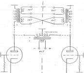
And if we use two SE output transformers each having two secondary windings with one pair shorted counter-phase and the speaker output taken from the other pair ?
(attached image, disregard the 'plate to plate winding' altogether).
http://www.diyaudio.com/forums/tubes-valves/217493-dual-se-amplifier-not-pse-take-two.html
After some years of investigation, conversations with transformer winders and EE of various lateral thinking guises, I surmise that 3H cancellation is simply not possible as presented in the original article.
However, there are some other interesting possibilities that might be worthy of investigation..
LH/S
Attachments
Last edited:
I asked this same question here a decade or so ago. The 2 SE OPTs do not share a magnetic field which a PP OPT will. So it works, but it is not PP.
dave
Isn't 2SE basically a bridged SE?
The previous thumbnail schematic with 2 secondaries per se transformer should have the speaker connected to the cross-wired secondaries. The other two secondaries can be eliminated.
Of course, the se transformers primary impedance, and secondary impedance must be
properly selected.
I have attached a schematic of a simple class A circuit that uses a pair of single ended output transformers. It is the minimum required to get this combination of 4 advantages:
No Magnetic Zero Crossing, but also having:
2nd harmonic distortion reduction due to push pull-like 2-phase output stage
Fairly symmetrical damping factor like class A push pull
More constant damping factor versus output swing like class A push pull
A class A single ended circuit has the advantage of no magnetic zero crossing, but does not have the other 3 advantages listed above.
A class A push pull circuit with push pull transformer does not have the advantage of no magnetic zero crossing, but it does have the other 3 advantages above.
Attachments
Thanks for telling me about the image!
I am still learning how to use the communication features of the forum.
So, I changed the text in my recent post before sending it, and merely referred to Ludwig Haus's earlier thumbnail.
My thumbnail looks OK in my browser (let me know if it is the one that is corrupted).
Now, for a brief follow-on:
Parallel single ended is implemented with:
two or more output tubes connected to a single output transformer primary
and the single secondary connected to the loudspeaker.
Bridged single ended is implemented with two single ended circuits, with
the secondaries connected in series. The signal phase of one secondary must be
in anti-phase with the other secondary signal. It can be implemented in many ways,
two phases driving two identical amplifiers, or a single phase driving amplifiers that reverse only one primary’s connections, or reversing only one secondary’s connections.
You will find my previous thumbnail schematic does not do either of the above.
It is not a parallel single ended amp, and it is not a bridged amp.
It can be argued by some that it is not push pull amp because it does not have a single push pull output transformer. I do not worry what to call it, I merely mention that it has a unique combination of advantages that I listed (and of course other disadvantages that I did not list).
that looks like short.
secondaries +spk all in series loop
First, just consider the transformers by themselves, but only one at a time.
The * markings on the transformers are the same phase.
The top connection of the primary * and the top connection of the secondary * windings are in phase with each other (just one transformer by itself; and then the other transformer by itself).
Then we have to consider what phase each is driven from (they are driven by opposite phases).
Now for the top sine wave:
The top tube grid voltage is going up, so the top tube plate voltage is going down (tube inversion of phase, in to out).
Since the top tube plate is going down, so are the primary * and secondary * connections of the top transformer going down with respect to ground.
Now for the bottom sine wave:
The bottom tube grid voltage is going down, so the top tube plate voltage is going up (tube inversion of phase, in to out).
Since the bottom tube plate is going up, so are the primary * and secondary * connections of the top transformer going up with respect to the ungrounded connection of that same secondary. But in this case, the secondary * connection is grounded. So the ungrounded “hot” connection of the bottom secondary is going down with respect to ground.
It is confusing, hard to describe, but true.
We have the top secondary * going down, which is connected to the bottom secondary going down (not the bottom secondary *). They are now in-phase, not shorted.
Just note as the top tube plate voltage is going down, the top plate current is going up.
And as the bottom plate voltage is going up, the bottom plate current is going down.
Hmmm, that is a lot like a push pull circuit.
Yes, the final output phase of the amp shown is out of phase with the original in phase input.
The final output phase is in phase with the anti - phase input signal. That is all easily corrected by the previous inversion(s) of the previous stages. I like to have my amplifiers in phase from input to output.
Excellent.
And if we use two SE output transformers each having two secondary windings with one pair shorted counter-phase and the speaker output taken from the other pair ?
(attached image, disregard the 'plate to plate winding' altogether).
http://www.diyaudio.com/forums/tubes-valves/217493-dual-se-amplifier-not-pse-take-two.html
After some years of investigation, conversations with transformer winders and EE of various lateral thinking guises, I surmise that 3H cancellation is simply not possible as presented in the original article.
However, there are some other interesting possibilities that might be worthy of investigation..
LH/S
Without using feedback, or special shaped feedforward compensation, third Harmonic distortion does not cancel.
Third harmonic signals do not cancel in push pull, nor in single ended, nor in the circuit that uses the cross wired SE transformer pairs.
The proof is in the formulas for triodes (Childs Law), pentodes, tetrodes, etc. as those formulas intersect with the Taylor Series Math function. Evens cancel, odds do not.
There was a report on a listening session of single ended, and push pull amplifiers.
The first picture and the story that goes with it gives one listener's reaction to Parallel Single Ended versus Push Pull: Vacuum Tube State of the Art Conference VSAC 2008 Report By Jeff Poth
There was a report on a listening session of single ended, and push pull amplifiers.
The first picture and the story that goes with it gives one listener's reaction to Parallel Single Ended versus Push Pull: Vacuum Tube State of the Art Conference*VSAC 2008 Report By Jeff Poth
I'll get back to the original positing when I have time, 'subtracted shorting' are the two words which come to mind at the minute WRT the diagram as posted. Based on the 'bridging mixer' circuit, its a bit left field but also sound in practice (hi Joe!)
So far as citing some random person/s subjective impression foe PSE vs PP, I would suggest this as invalid for anything other than 'another persons subjective impression'..
Having had built it both ways, I know which I prefer (well, mostly).. and I should assume that you have done the same to your own preference, or not?
LH/S
Last edited:
So far as citing some random person/s subjective impression foe PSE vs PP, I would suggest this as invalid for anything other than 'another persons subjective impression'..
My biz partner came back from that VSAC and his subjective opion was that the Vacuum State PP 300B was the best amp he heard there
Another person's subjective impression
")
dave

- Status
- This old topic is closed. If you want to reopen this topic, contact a moderator using the "Report Post" button.
- Home
- Amplifiers
- Tubes / Valves
- Two SE OPT -> one PP OPT?