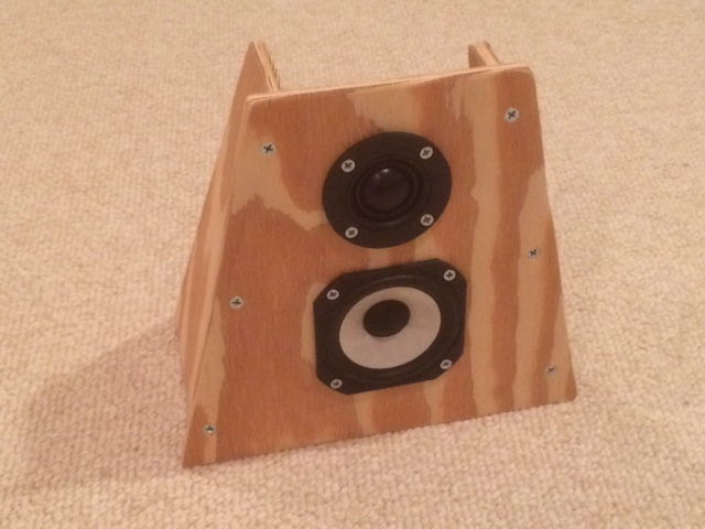
I'm going to replace the satellites of my old hercules 2.1 system with DIY speakers using the 10F-8414 and the ND25FA-4. The "subwoofer" of the system plays till about 200Hz so should match up with the 10F in a closed box.

I have been playing around with Xsim to simulate a passive crossover and after fiddling about for a while this is the best I got. I'm aiming for acoustical point of crossover between 3k and 4k, since they'll be used near field on a desk I'm not very concerned about power response (but concerned enough to use a tweeter ) and the 10F plays cleaner then the ND25FA.

Following the KISS principle I only used a series notch to tame the nd25FA rising frequency at 15kHz.
Seeing as this is the first passive crossover I simulated I have some further questions. The order of the components doesn't matter does it? For the tweeter section resistor-->2nd order highpass-->notch filter or is there a reason I should go for a particular order?
What is acceptable as far as impedance peaks and phase rotation? I wanted to keep the impedance up since they'll be driven by the built in amp of the hercules system.
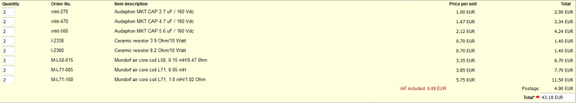
What quality of components would you recommend (and where would i get them, strassacker, falcon?) Searching the web I found resistors doesn't matter much, air-core for coils (although at 10W max power I don't think it matters much) and no electrolytic caps and a whole bunch of voodoo sprinkled with magic fairy dust about other flavors.
If i use cheap electrolytic caps crossover cost is about 30€ delivered. I included the zma and frd files for the 10F and ND25FA as measured in the box for those who want to play along.
Crossover layout: keep coils and caps that aren't doing the same thing 90° rotated vs each other. Any other big no no's?
What type of screws do i need to screw the crossover board to the dynavox speaker binding post backside?

I have been playing around with Xsim to simulate a passive crossover and after fiddling about for a while this is the best I got. I'm aiming for acoustical point of crossover between 3k and 4k, since they'll be used near field on a desk I'm not very concerned about power response (but concerned enough to use a tweeter
) and the 10F plays cleaner then the ND25FA.
Following the KISS principle I only used a series notch to tame the nd25FA rising frequency at 15kHz.
Seeing as this is the first passive crossover I simulated I have some further questions. The order of the components doesn't matter does it? For the tweeter section resistor-->2nd order highpass-->notch filter or is there a reason I should go for a particular order?
What is acceptable as far as impedance peaks and phase rotation? I wanted to keep the impedance up since they'll be driven by the built in amp of the hercules system.
What quality of components would you recommend (and where would i get them, strassacker, falcon?) Searching the web I found resistors doesn't matter much, air-core for coils (although at 10W max power I don't think it matters much) and no electrolytic caps and a whole bunch of voodoo sprinkled with magic fairy dust about other flavors.
If i use cheap electrolytic caps crossover cost is about 30€ delivered. I included the zma and frd files for the 10F and ND25FA as measured in the box for those who want to play along
.Crossover layout: keep coils and caps that aren't doing the same thing 90° rotated vs each other. Any other big no no's?
What type of screws do i need to screw the crossover board to the dynavox speaker binding post backside?
Attachments

In case you haven't set the correct woofer distance, here is a guide.
A Speaker Maker's Journey: LM-1 Testing Driver Distances
A Speaker Maker's Journey: LM-1 Testing Driver Distances
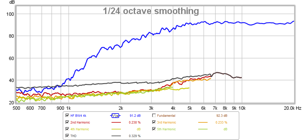
Nice design. I used almost the same drivers in a small OB with great results. I had the TG9FD which is the lower cost fiberglass sibling of the 10F with a similar sound. I recall the ND25FA having a very flat response but likes to be crossed high to avoid distortion. 3k is good but 4K would be even better.
http://www.diyaudio.com/forums/multi-way/280968-ob-compact-3way-nearfield-monitor-13.html
http://www.diyaudio.com/forums/multi-way/280968-ob-compact-3way-nearfield-monitor-13.html
I recall the ND25FA having a very flat response but likes to be crossed high to avoid distortion. 3k is good but 4K would be even better.
I agree. 4k+ sounds better if the midbass can do it. I built my Synchaetas with the ND25 and the PRV 4MR60-4, and they are very potent little 2 ltr monitors.
Also of note- I would worry about the top-end rise. A series pad resistor, and a 12dB electrical is really all that's needed.
Later,
Wolf
@ eriksquires: I did not include the acoustical offset in the previous simulation. Since I don't have a cap I can estimate the delay using some sweet sweet trigoniometry. The tweeter is 6.1mm outside the baffle, the 10F dustcap is about 8mm inside the baffle. This gives 23.8mm delay for the woofer as measured at 0.5m on tweeter axis. I'll include it in the next sim.
Thanks Xrk, Inductor and Wolf_teeth. I tried getting the acoustical crossover point higher but the bump in respons of 10F at 1.8K made it difficult. I'll see if I can get it higher. I liked the mini-OB but it is much too wide to fit on my desk at the moment.
@ wolf_teeth: you said "I would worry about top-end rise" did you mean "wouldn't"
Or you can make a stepped baffleThe tweeter is 6.1mm outside the baffle, the 10F dustcap is about 8mm inside the baffle. This gives 23.8mm delay for the woofer as measured at 0.5m on tweeter axis. I'll include it in the next sim.
Or put the 10 F above the tweeter ( just turn upside down the cabinet
)Or just leave it like it is
The 10F got an acoustical offset of 0.94 inches and I fiddled with the values to get an acceptable 4K crossover.
With notch to tame rising tweeter respons

And without notch

The rising treble seems very familiar to but not as bad as the monitor audio silver S2 (which I like very much) I built a new cabinet for:

Thats a 10dB rise from 5K to 17K and then it just shoots through the roof.
Just leave out the series notch?
With notch to tame rising tweeter respons
And without notch
The rising treble seems very familiar to but not as bad as the monitor audio silver S2 (which I like very much) I built a new cabinet for:
Thats a 10dB rise from 5K to 17K and then it just shoots through the roof.
Just leave out the series notch?
To calculate the offset see here: How to use OmniMic and PCD to find the Relative Acoustic Offset - Techtalk Speaker Building, Audio, Video Discussion Forum
I think your value is a bit too high but in the ballpark. You cannot neglect the offset as it has a high effect on the chosen crossover point.
Ralf
I think your value is a bit too high but in the ballpark. You cannot neglect the offset as it has a high effect on the chosen crossover point.
Ralf
I was talking about polar response BTW
I'd like to design it for flat on tweeter axis, I can always point it up. If I design it for flat at an arbitrary higher position I would need a redesign if I change desk and or chair.
For some weird reason I have it in my head that it would sound worse for the tweeter. Can't really explain the reasoning behind it. In any case I'll get some higher output from the woofer since I did the measurements on a stand instead of on a desk to get rid of the huge interference dip when I measured with mic and speaker on the table the first time.
@ Giralfino: I used sketchup to calculate the distances. The distance of the tip off the dome for ND25Fa-4 is given in the pdf, I used a ruler to measure the depth of the dustcap of 10F. I'm assuming they are close enough to the acoustical center for these calculations.
@ Giralfino: I used sketchup to calculate the distances. The distance of the tip off the dome for ND25Fa-4 is given in the pdf, I used a ruler to measure the depth of the dustcap of 10F. I'm assuming they are close enough to the acoustical center for these calculations.
Last edited:
It's true because of the much shorter wavelengths involved, thus you'll get nulls and bumps from destructive or constructive interference.For some weird reason I have it in my head that it would sound worse for the tweeter. Can't really explain the reasoning behind it.
It's not as simple as that. It is acoustical offset and not mechanical. I suggest you find the exact value with the method described in the document linked, you only need excel to run PCD.I used sketchup to calculate the distances.
Ralf
The method suggested above to calculate the acoustic offset is critical to getting an accurate simulation of the crossover. You can do it with Xsim but Xsim doesn't have the built in vertical and axial offset so you need to use trigonometry to calculate the line of sight offset. For the 10F and ND25 I would guess the offset is closer to 15mm to 20mm. Mechanically it is close to the difference in the axial location of the voice coils as a starting point. When you can show that the simulation can predict the summed response of the tweeter and mid exactly (every little peak dip and bump within 0.25dB) by simply adjusting acoustic offset - then you know the sim works. Then applying filters will now be predictively quite accurate.
Measure response from mid and tweeter by themselves full range and then tie together in parallel and measure again. Make sure all 3 measurements the mic and speaker are not touched. Only disconnect and reconnect wires remotely. This is an acoustic interferometry measurement so it's critical nothing is touched as motions below 1mm are resolvable.
Then convert measured responses to minimum phase. Only way I know how to do this in REW is tedious but works: export to minimum phase impulse .wav file. Close measurement and import WAV file. Then export the frequency response (and it's associate phase) as .txt then rename as .frd.
Import that into Xsim or PCD.
- Status
- This old topic is closed. If you want to reopen this topic, contact a moderator using the "Report Post" button.
- Home
- Loudspeakers
- Multi-Way
- PC desktop speakers