Hello,
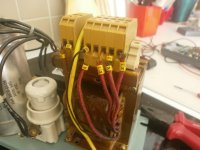
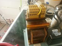
I recently got a power supply in my hands that I would like to know more about. Here´s couple of images of the wiring.
There was also a 26500uf 60V cap attached to the assembly as well as a socket with a 10A fuse in it. These were not connected in the transformer.
I would like to know about the markings to set this thing up for measurements to know what it is good for.
The wiring goes as follows with the markings.:
Left side of the transformer - WIRE no1 -> "a"
Left side of the transformer - WIRE no2 -> "x"
Right side of the transformer - WIRE no1 ->"X3"
Right side of the transformer - WIRE no2 ->"X2"
Right side of the transformer - WIRE no3 ->"X1"
Right side of the transformer - WIRE no4 ->"A"
Right side of the transformer - WIRE no5 ->"m" -> connected to ground via the yellow cable.
Thanks for any help in advance!
K
Attachments
Possibly 3 phase? X1, X2, X3,
neutral A and screen M?
Thanks!
So the two wires on the left, "x" and "a" are assumably the primary?
And how would I go by measuring the secondary?AC voltage between "X1/X2/X3" and "A"?
K
X and A are secondary. It will not work unless connected to a three phase supply.
So it´s like http://trackeripm.us/wp-content/uploads/2013/02/PowerSupply-1P.png ?
Shouldn´t it have three cores/coils?
K
Indeed.So it´s like http://trackeripm.us/wp-content/uploads/2013/02/PowerSupply-1P.png ?
Shouldn´t it have three cores/coils?
K
the shape tells us it is a single phase transformer.
It could be designed for a voltage from two phases, i.e. sqrt(3)*230Vac = 400Vac single phase, instead of the more normal 230Vac.
Thinking about it, you could be right in which going by the labelling is not good enough.
Is there a manufacturers number anywhere?
There´s only a making "SMDA 31A" which is the model of the PSU. It´s a 24V/5A power supply. I can´t get through to any more information right now. I searched it through google.
Indeed.
the shape tells us it is a single phase transformer.
It could be designed for a voltage from two phases, i.e. sqrt(3)*230Vac = 400Vac single phase, instead of the more normal 230Vac.
I first thought it would´ve had 3 secondary windings but then thought of the possibility of 3 input voltages. I´ve seen these before that have had 230V and 120V inputs.
Yes, a 3 phase laminated core transformer has three limbs with one phase on each limb...............I first thought it would´ve had 3 secondary windings ..............
Toroid 3 phase use three compeletely separate toroids.
AS you thought first time around the shape in the pic cannot be a 3 phase transformer.
Yes, a 3 phase laminated core transformer has three limbs with one phase on each limb.
Toroid 3 phase use three compeletely separate toroids.
AS you thought first time around the shape in the pic cannot be a 3 phase transformer.
I´m not sure if I´m following. Is your opinion at this time that it has 3 secondary windings?
The two windings on the left side come out as wires much thicker than any on the right side. So this would indicate a lot more current is running on this side through these two wires.
K
As you can see connection "A" has one wire and "X1" has two.
I think "X2" has also two and "X3" one again, invisible on the photo.
If that is the case probably "A" is the start and "Xx" are tabs to select the wanted output voltage. (adjustements for deviations in means voltage ?)
Mona
I think "X2" has also two and "X3" one again, invisible on the photo.
If that is the case probably "A" is the start and "Xx" are tabs to select the wanted output voltage. (adjustements for deviations in means voltage ?)
Mona
As you can see connection "A" has one wire and "X1" has two.I think "X2" has also two and "X3" one again. If that is the case probably "A" is the start and "Xx" are tabs to select the wanted output voltage.
This is exactly the case. Can you elaborate a little more how did you come to this conclusion based on the amount of the wires?
(adjustements for deviations in means voltage ?)
This I didn´t quite undesrtand. Sorry for my english.
K
It is not a 3phase transformer.I´m not sure if I´m following. Is your opinion at this time that it has 3 secondary windings?
The two windings on the left side come out as wires much thicker than any on the right side. So this would indicate a lot more current is running on this side through these two wires.
K
It has to be a single phase transformer.
I have not tried to count windings.
I have not tried to count windings.
That was just for Ketje for the inquiry of the wire on the assumed secondary windings.
I thought I could use this transformer for tube heaters in some bigger project since it´s rated for 5A in current.
K
Well I suppose the "X" stands for the unknown.Take X1,X2 or X3 depending on the input voltage to get it right.This is exactly the case. Can you elaborate a little more how did you come to this conclusion based on the amount of the wires?
This I didn´t quite undesrtand. Sorry for my english.
K
With Vin=230V you get on X2 the correct output.If somewhere Vin=220V take X3 and if Vin=240V take X1 for the same Vout.
But it's just maybe ! I don't know that transformer .
Mona
Identify the windings and which tappings are on which windings.
Some windings may have more than two tappings.
example: a multi-tapped primary could have 0-100-110-120Vac
The other primary could be exactly the same.
Wiring those in series allows tappings to suit 200, 210, 220, 230 and 240Vac.
One selects the tapping to suit the supply voltage ±5Vac.
Some windings may have more than two tappings.
example: a multi-tapped primary could have 0-100-110-120Vac
The other primary could be exactly the same.
Wiring those in series allows tappings to suit 200, 210, 220, 230 and 240Vac.
One selects the tapping to suit the supply voltage ±5Vac.
No word from the manufacturer yet. But I did the measurements between the posts and here´s what I got:
Continuity between "x" and "a" - DC Resistance approx. 1.0ohm - No further continuity
Continuity between "A", "X1", "X2" and "X3" - DC Resistances approximately:
X1 - A 9.0ohm
X1 - X2 1.9ohm
X1 - X3 3.0ohm
X2 - A 10.0ohm
X2 - X3 1.8ohm
X3 - A 15.0ohm
"m" has no contiunuity with anything so I assume that´s just shield.
Can anyone make anything from these figures?
K
that means that X1 and X2 and X3 and A are all tappings on the same winding.
Is there another winding?
I can see that the order of the tappings using your very inaccurate resistance measurements is A - X1 - X2 - X3
A - X1 is < 9r
A - X2 is < 10r
A- X3 < 15r
X1 - X2 must be pretty short showing 1r9, maybe a real 1r0?
X2 - X3 is also pretty short showing 1r8, maybe a real 1r0.
That leaves X1 to X3 @ ~ 2r0. and you measured 3r0.
It looks like your ohm-meter is reading about 1ohm too high.
Did your check your ohm-meter before and after these measurements?
How did you measure 15r for when you should be getting 9.0ohms (maybe a real 8r0)+3.0ohms (maybe a real 2r0) = 12.0ohms (whuch should equal a real 10r0 and add on your over-read to get 11ohms).
You need to do a probe to probe measurement and see if it consistently reads the same internal + leads resistance. If it keeps changing, then it is no good for measuring resistance. You must get repeatability, or it is useless.
- Status
- This old topic is closed. If you want to reopen this topic, contact a moderator using the "Report Post" button.
- Home
- Amplifiers
- Power Supplies
- Help Identyifying Power Transformer?