Hi Guys,
As a newbie here, I am currently designing a two way series crossover.
I am using HIVI F6 as woofer and TW025m1 as tweeter, the graphes of which show, best and recommend cross over is around 2-2.2K, a bit below the tweeters and perfectly fit F6.
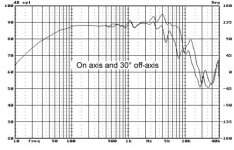
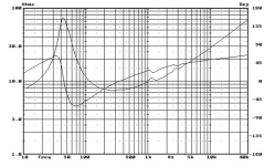
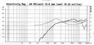
In this case, I believe a 2nd order would be good, therefore I have come up with an idea like this, which a modified version of LCAudio:
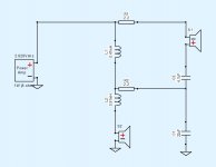
This is from a fine tuning using Xsim with initial numbers from online calculators, which is for parallel only but as said parallel and series has the same math. (I am yet to find a sxo calculator.)
The impedances used here are from actual SPLtracing, which, at 2200hz, are 12.9ohms and 8.1ohms for F6 and TW025M1. (I am not a fan of Zobel, because I think it is approximate anyway.)
The simulate result is as following, I believe I have got a very close 2nd order.
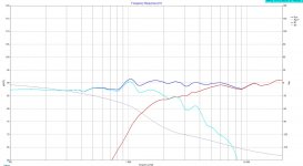
My question is, is this really going to be like this in reality?
Regards,
Jing
As a newbie here, I am currently designing a two way series crossover.
I am using HIVI F6 as woofer and TW025m1 as tweeter, the graphes of which show, best and recommend cross over is around 2-2.2K, a bit below the tweeters and perfectly fit F6.


In this case, I believe a 2nd order would be good, therefore I have come up with an idea like this, which a modified version of LCAudio:

This is from a fine tuning using Xsim with initial numbers from online calculators, which is for parallel only but as said parallel and series has the same math. (I am yet to find a sxo calculator.)
The impedances used here are from actual SPLtracing, which, at 2200hz, are 12.9ohms and 8.1ohms for F6 and TW025M1. (I am not a fan of Zobel, because I think it is approximate anyway.)
The simulate result is as following, I believe I have got a very close 2nd order.

My question is, is this really going to be like this in reality?
Regards,
Jing
Hi Jing,
XSim is nearly 100% accurate when measurements were taken from drivers in cabinets.
Otherwise, taking SPL traces is just approximate, especially since you don't have any acoustic distances.
If this is a 2 way, estimate about 1.2 to 1.4" distance. Tune the woofer and set the distance to that, then revisit your crossover. This will give you a better indicator of your complexities.
Zobels are wonderful things, but the online calculators may not be. As important as the frequency effects of Zobel's are the phase shifts that may help you align the drivers. I often bump the cap or resistor to finish tuning that. Zobels can be very useful, don't become snobby about circuits. Sometimes you need them and sometimes you don't, that's all. I usually just use XSim's impedance chart to create an accurate Zobel. Connect the woofer by itself, and adjust the C and R values until the impedance plot after the resonance peak is flat. That's where to start.
Best,
Erik
Last edited:
Hi Jing,
XSim is nearly 100% accurate when measurements were taken from drivers in cabinets.
Otherwise, taking SPL traces is just approximate, especially since you don't have any acoustic distances.
If this is a 2 way, estimate about 1.2 to 1.4" distance. Tune the woofer and set the distance to that, then revisit your crossover. This will give you a better indicator of your complexities.
Zobels are wonderful things, but the online calculators may not be. As important as the frequency effects of Zobel's are the phase shifts that may help you align the drivers. I often bump the cap or resistor to finish tuning that.
Best,
Erik
Sorry Erik, I am not quite sure about your reply. SPLtrace is to trace the curve measured by manufacture, and it can be very close if plotted with patience.
Often see people use DC resistance and a Zobel to do the same job but I doubt how much more accurate that can be.
When you talk about distance, do you mean I need measure the frequency response from a distance?
Regards,
Jing
Jing,
SPL charts provided by manufacturers are often just a part of their advertising. They won't have told you how the drivers are measured, or whether there has been any smoothing applied to the chart.
Regarding "Often see people use DC resistance and a Zobel to do the same job but I doubt how much more accurate that can be" - I have absolutely no idea what you are talking about. I am fairly sure that very few people will try to design a crossover based on the DC resistance of a driver, and I'm fairly sure (unless you are a mystic) that designing a Zobel (to do what?) based on DC resistance is an impossible exercise.
You seem fixated on a series crossover, instead of a parallel one. Is there any particular reason for this? Both have their own complexities, but in general, the different sections of a parallel crossover are transferable with the driver, while the series crossover is a wholistic design.
Hi Jing,
Sorry for the confusion. What I meant was, if you measure things yourself, then XSim is very close. By this I mean that you use a microphone and OmniMic or Room EQ Wizard In this case XSim will be nearly 100% accurate. On the other hand, tracing from a picture, using any of the free tools like SPL Copy or SPLTrace or whatever is worth doing when you are trying to choosing matching drivers but not beyond.
Since the manufacturers usually plot on an infinite baffle, you must measure a woofer in place to get the most accurate bass and slope for it. This way the effects of your speaker box's volume and baffle will be taken into consideration when you design your crossover.
In terms of measuring speaker distances, in most two ways this means that the woofer's signal will arrive a little after the tweeter. You must know exactly what this delay is in order to be able to create a reasonably accurate crossover. This is why just copying SPL and impedance traces won't give you a final answer. Please see my blog post here.
I am no longer sure what you are talking about in terms of a Zobel. The common use is to maintain the driver impedance over a wide range. This makes the low pass circuit consistent. Otherwise the slope of the low pass can get more and more shallow as the driver impedance increases. However, whether or not it makes a difference in any given speaker varies. I've made some speakers with them, and some without. Depends on how soon and how fast the woofer impedance rises.
The Zobel also has phase shifting effects which may be beneficial or destructive, so that matters more than having an absolutely flat impedance curve.
Best,
Erik
Hi Jing,
Sorry for the confusion. What I meant was, if you measure things yourself, then XSim is very close. By this I mean that you use a microphone and OmniMic or Room EQ Wizard In this case XSim will be nearly 100% accurate. On the other hand, tracing from a picture, using any of the free tools like SPL Copy or SPLTrace or whatever is worth doing when you are trying to choosing matching drivers but not beyond.
Since the manufacturers usually plot on an infinite baffle, you must measure a woofer in place to get the most accurate bass and slope for it. This way the effects of your speaker box's volume and baffle will be taken into consideration when you design your crossover.
In terms of measuring speaker distances, in most two ways this means that the woofer's signal will arrive a little after the tweeter. You must know exactly what this delay is in order to be able to create a reasonably accurate crossover. This is why just copying SPL and impedance traces won't give you a final answer. Please see my blog post here.
I am no longer sure what you are talking about in terms of a Zobel. The common use is to maintain the driver impedance over a wide range. This makes the low pass circuit consistent. Otherwise the slope of the low pass can get more and more shallow as the driver impedance increases. However, whether or not it makes a difference in any given speaker varies. I've made some speakers with them, and some without. Depends on how soon and how fast the woofer impedance rises.
The Zobel also has phase shifting effects which may be beneficial or destructive, so that matters more than having an absolutely flat impedance curve.
Best,
Erik
Hi Erik,
Thanks for the much elaborated reply.
Look, I am by no means trying to make a pair of perfect sounding speakers. To be honest, judging from the drivers data, what I might get will not be perfect no matter how accurate the math is and how hard I try.
What I am trying to do is to use limited tools and basic methods to make it sound comfortable to a degree that the drivers's nature allows.
I have heard that series xo can have a reasonable flat curve with much tolerance of the components, whereas a parallel xo does the opposite.
Therefore, series is my choice.
Jing,
SPL charts provided by manufacturers are often just a part of their advertising. They won't have told you how the drivers are measured, or whether there has been any smoothing applied to the chart.
Regarding "Often see people use DC resistance and a Zobel to do the same job but I doubt how much more accurate that can be" - I have absolutely no idea what you are talking about. I am fairly sure that very few people will try to design a crossover based on the DC resistance of a driver, and I'm fairly sure (unless you are a mystic) that designing a Zobel (to do what?) based on DC resistance is an impossible exercise.
You seem fixated on a series crossover, instead of a parallel one. Is there any particular reason for this? Both have their own complexities, but in general, the different sections of a parallel crossover are transferable with the driver, while the series crossover is a wholistic design.
At least you need a constant value to design the Zobel, right? As the impedance is changing, what are you going to use? The one at xo point?
Jing
Technically, Zobel compensation means bringing the impedance to a consistent and resistive nature and with speakers this usually means one specific thing, ie the top half of a woofer's impedance with the highest practical value as the result, so there are usually fixed formulas for this.At least you need a constant value to design the Zobel, right? As the impedance is changing, what are you going to use? The one at xo point?
Jing
This makes crossover design easier when done by hand.. usually a well crafted crossover won't use these values, but it doesn't matter as there is more than one way to achieve the same result.
Parallel is not the opposite, it is more like freestyle design on each driver.I have heard that series xo can have a reasonable flat curve with much tolerance of the components, whereas a parallel xo does the opposite.
Therefore, series is my choice.
If simplicity is your aim then you have made a reasonable choice. If I were going to do a series design it would include some extra elements in the parallel crossover style. At least the option is there.
Parallel is not the opposite, it is more like freestyle design on each driver.
If simplicity is your aim then you have made a reasonable choice. If I were going to do a series design it would include some extra elements in the parallel crossover style. At least the option is there.
Interesting, as so much info says that. But I am not sure as I am no expert.
I have also tried in this design an Lpad to bring down 4db difference of the tweeter, and An Zobel to compensate the woofer, as often seen in a pxo, but it appears on the graph not much difference.
That is why I am asking the question, that how accurate Xsim would be.
Last edited:
Exactly.
And since the FR imported into it aren't good, the outcome is totally wrong.
It has mentioned here before, but it seems that the info has not been digested by the OP, so here goes again: you cannot use as-is a FR from a datasheet. Period. It has to be manipulated before it can be used with a crossover simulator because when placed on a baffle, the baffle itself distorts the FR of the driver with basically two effects: baffle step and diffraction. Search about the baffle step effect, but basically the baffle step produces a loss of response below the baffle step point, so if not taken into account the speaker will have too much midrange and treble and too low bass. The diffraction (and the bump above the baffle step point), can have a negative effect on the FR with bumps and dips, that if not taken into account and placed in the wrong place, can have negative effects on the sound.
The good news is that there are free tools able to take into account all those effects. See here for a tutorial: http://audio.claub.net/software/DaveDalFarra/Simple%20Loudspeaker%20Design%20ver2.pdf
and here for the software needed: software
The acoustic delay between woofer and tweeter can be taken into account when you calculate the minimum phase, or inserted into Xsim. Of course don't do both
Ralf
I think that the combination of drivers chosen is very hard to implement. For a first speaker design I'd opt for a 5.25"+1" with a more easy mid-woofer (i.e. one without breakup under 6KHz), and in this case the Audax tweeter could be fine.
I would trust the accuracy of xsim to be as good as the information you feed it.
Thanks for the reply.
At the moment, I only have SPLtraced FR at hand, so far will trust it until I got something better.
Just say, assume this FR is correct, would this design be OK?
Exactly.
And since the FR imported into it aren't good, the outcome is totally wrong.
It has mentioned here before, but it seems that the info has not been digested by the OP, so here goes again: you cannot use as-is a FR from a datasheet. Period. It has to be manipulated before it can be used with a crossover simulator because when placed on a baffle, the baffle itself distorts the FR of the driver with basically two effects: baffle step and diffraction. Search about the baffle step effect, but basically the baffle step produces a loss of response below the baffle step point, so if not taken into account the speaker will have too much midrange and treble and too low bass. The diffraction (and the bump above the baffle step point), can have a negative effect on the FR with bumps and dips, that if not taken into account and placed in the wrong place, can have negative effects on the sound.
The good news is that there are free tools able to take into account all those effects. See here for a tutorial: http://audio.claub.net/software/DaveDalFarra/Simple%20Loudspeaker%20Design%20ver2.pdf
and here for the software needed: software
The acoustic delay between woofer and tweeter can be taken into account when you calculate the minimum phase, or inserted into Xsim. Of course don't do both
Ralf
I think that the combination of drivers chosen is very hard to implement. For a first speaker design I'd opt for a 5.25"+1" with a more easy mid-woofer (i.e. one without breakup under 6KHz), and in this case the Audax tweeter could be fine.
Thanks Ralf,
I will eventually to add another .5 way for the baffle step compensation.
Anyway, now according to what you said here, would a cross point at 4K good enough?
The Audax recommended 4K with 12db slope, but here 2.2K is recommended for a F6. I would like to use 12db slope too to avoid that two humps after 2.2K.
Will this do? Very hard to decide which way to go.
Jing
As a learning or teaching exercise - what you are doing is good as you are learning the process and mechanics of designing a crossover. The effects of baffle step loss and diffraction on a typical 8in to 12in wide box is going to be of order 5dB. So designing a xo this way will get you an approximate starting point within 5dB. That may be good enough but you will need to make a measurement on the actual baffle with the actual drivers to get the phase information so that you can set the correct time/phase alignment so that at the XO region the signals combine as you expect.
The process you are doing now is good to get a rough idea of whether or not the driver is a suitable fit from the standpoint of sensitivity and frequency response. It will allow you to make a decision of whether or not buy the driver. Once they show up mount them in the box and make the real measurement with a calibrated mic. You need 3 measurements: one with just woofer connected, one with just tweeter connected, a one with both in parallel. It's critical that all 3 measurements are made without physically moving the speaker or mic - just switch wires carefully. The import the minimum phase FRD files into Xsim (or PCD - another excellent tool by Jeff Bagby). The data now gives you info to use acoustic interferometry to calculate the acoustic offset (distance from where the voice coil source of the sound originates relative to each other) exactly to 1mm accuracy. This is needed to design the xo phase response properly.
So don't abandon what you are doing with tracing FR plots from manufacturer if you are still in the search mode for drivers. If you have already bought drivers and MUST use them, then the next step is to make measurements in the as-built baffle or box.
Probably.Just say, assume this FR is correct, would this design be OK?
Designing a crossover using a response measurement from each driver is not the last word in crossover design but it is a fair step in the right direction, and a big one as far as the learning curve is concerned.
Also as far as the speaker design is concerned, a crossover can compensate for, but not fix, most errors.
Read here until the 4th image (and look at the images) and judge by yourself if the effect of diffraction/baffle step (it is the same effect) can be ignored and only cured by a 0.5 way approach: https://trueaudio.com/st_diff1.htmI will eventually to add another .5 way for the baffle step compensation.
I would simulate the effect of the baffle, add the proper phase (I suspect you don't have phase data in your frd and zma), and then design an appropriate crossover. Without simulation first you are essentially shooting in the dark.
Audax doesn't recommend a 4KHz crossover point, it merely says what power handling you can expect with it with a 2nd order electrical filter. If you want to use that tweeter, mate it with an easy 5.25" mid-woofer (for example a Peerless 830656 or a SS Discovery 15W) and cross over at around 3KHz. OTOH if you want to use your 6" driver, mate it with a robust tweeter and cross over at 2KHz or better under.
Another thing to add, is that what is important in a crossover is the acoustic slope and not the electrical slope. In my experience it is pretty easy to achieve good LR4 acoustic slopes (4th order LR), with a 2nd order electrical on the woofer and 3rd order electrical on the tweeter. See here for an example and please read the crossover section: Zaph|Audio - 4" Bargain Mini
Ralf
Jing,
I really think you may be better off makign a pre-designed 2 way kit. At the very least, please take a look at the LM-1 here to get a completed kit design. I can share the XSim for it and you can examine each of the components needed to get to a finished crossover.
Best,
Erik
I really think you may be better off makign a pre-designed 2 way kit. At the very least, please take a look at the LM-1 here to get a completed kit design. I can share the XSim for it and you can examine each of the components needed to get to a finished crossover.
Best,
Erik
I have heard that series xo can have a reasonable flat curve with much
tolerance of the components, whereas a parallel xo does the opposite.
Therefore, series is my choice.
Hi,
That is true for 1st order series *, but exactly the opposite for 2nd order.
The point is whether the final x/o component is in parallel or series with
the drivers. Parallel is what you want, and is true for odd order series,
and true for even order parallel.
Therefore for 2nd order electrical you choose parallel.
And read up on diffraction / baffle step effects, your ignoring them.
rgds, sreten.
* 1st order series has limited use but is ideal for FAST's
with well chosen drivers, with different sensitivities x/o
at or near the baffle step mid frequency.
Last edited:
- Status
- This old topic is closed. If you want to reopen this topic, contact a moderator using the "Report Post" button.
- Home
- Loudspeakers
- Multi-Way
- A two way 2nd order series crossover design