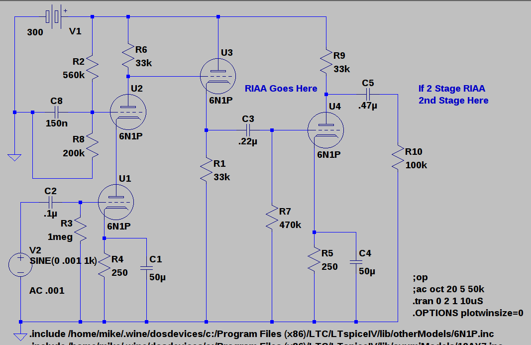
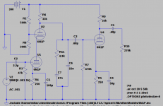
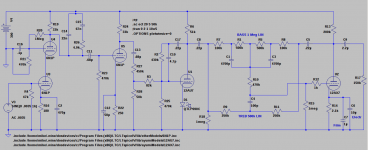
How about this basic structure for phono preamp? gain should be between 70 and 80 dB before EQ curve losses. if single stage EQ is used it would be between the CF and final output tube. if two stage would be split between there and after last tube (load would be line stage input or possibly another follower).
Attachments
Looks reasonable, although one of the nice things about the cascode is it's well defined output resistance. You could therefore drive the RIAA network directly from the cascode, and move the cathode follower to the output for driving cables. Also, remove C8 for improved PSRR! 
Also, remove C8 for improved PSRR!
Will that increase circuit noise since most of the first stage gain comes from the upper tube?
No, most of the noise always comes from the lower tube.Will that increase circuit noise since most of the first stage gain comes from the upper tube?
Thanks guys. I have a knee replacement scheduled for June 6 and I will be off work for a couple of months so I want a couple of projects using mostly what I have on hand.
I thought C8 would help keep PS noise out but I plan to do a simple'ish MOSFET regulated B+ to improve filtering.
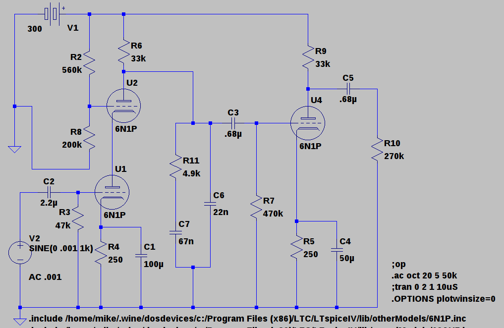
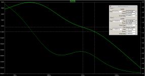
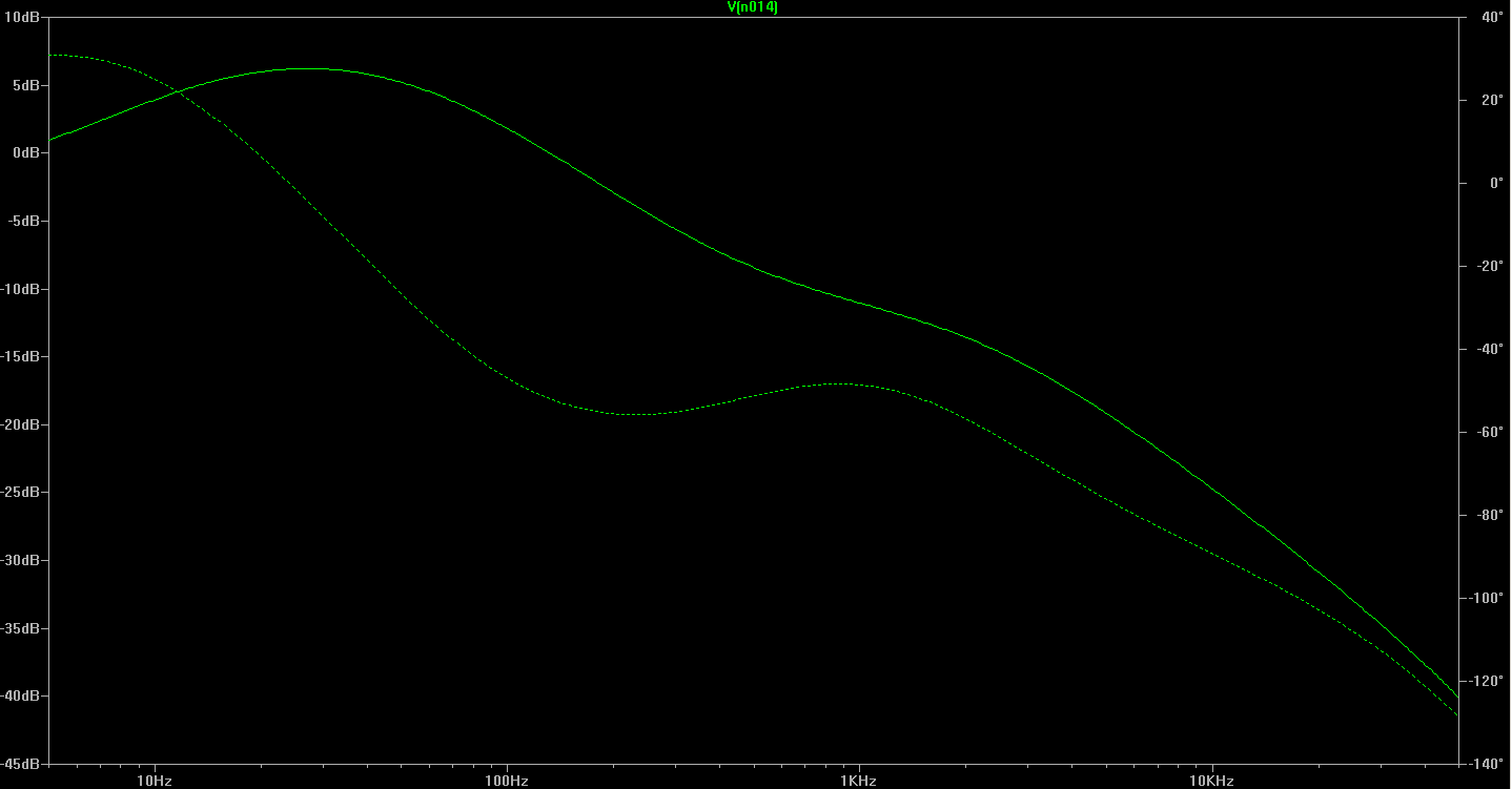
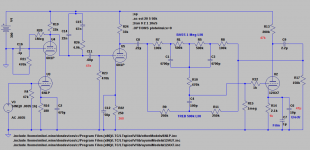
Here is a shot at a single stage version. Input signal is at -60dB so gain at 1K is about 51dB. Should be reasonable for most MM carts right?
I thought C8 would help keep PS noise out but I plan to do a simple'ish MOSFET regulated B+ to improve filtering.
Here is a shot at a single stage version. Input signal is at -60dB so gain at 1K is about 51dB. Should be reasonable for most MM carts right?
Attachments
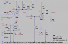
The Cascode has bad Power Supply Rejection Ratio (PSRR).
The top tube has very little gain (less then 3 is sugested by Merlin in his new HiFi preamp book). Removing C8 allows "feed forward" of some of the power supply noise to the top tube which acts to cancel some of the residual power supply noise at the top tubes anode.
The R2 to R8 ratio shown is about right to get the feed forward anti phase noise level to cancel that power supply noise.
One of the many things explained in this
http://www.diyaudio.com/forums/tubes-valves/286683-merlins-new-hi-fi-valve-preamp-book-released.html
RECOMMENDED - I have had my copy for a week and am commencing the 2nd reading. In particular I'm looking at the section on cascodes in the book examining a JFET Triode cascode (J113 + 6SL7) as an input stage for my latest Git Amp. I will be using that same noise "feed forward" technique.
Cheers,
Ian
Last edited:
My two cents
Values according to Russian 6N1P data, Svetlana data is different !
The DC feedback from the anode gives an automatic division of the supply voltage over the two tubes.Now you need the decoupling C to avoid AC feedback.I prefer the RIAA filter on the upper side, like that the power supply is not part of it.Now the power is in between the output of the filter and the next stage, no influence on the filter.
Mona
Attachments
So if I am following you correctly Ian you are saying I accidentally got the ratio about right so that the noise at the grid will approximately cancel that injected at the anode right? The accidental Akido?
Mona, I don't quite follow what your saying the cap and AC feedback. Will think it over and see if I can figure it out. As to the filter ground I always forget that the PS is also a signal ground, Does its effectiveness as such change with regulated PS v.s. unregulated?
Mona, I don't quite follow what your saying the cap and AC feedback. Will think it over and see if I can figure it out. As to the filter ground I always forget that the PS is also a signal ground,
Does its effectiveness as such change with regulated PS v.s. unregulated?It's not the stability of the supply but the quality of the decoupling that counts.
And without the C on the grid of the upper triode 1/3 of the anode AC is fed back to the grid, leaving not much gain.
The lower triode has a voltage gain of allmost none, the load is the cathode-impedance of the upper one.But it does voltage to current.The upper triode does all the voltage gain with current unchanged.Not decoupling the grid is no good !
Total voltage gain of the hole stage is transconductance of the lower triode multipied by the anode load.There is a trade-off for the bias current, more to get more transconductance and for the voltage drop on the anode resistor not to much resulting in a too low anode voltage.
Mona
OK, I just. Noticed you are doing something entirely different at the grid of the upper tube. I was just using a voltage divider from B+ to ground to set the operating voltage while you are actually setting up feedback from the anode to grid. What is.the advantage of that approach?
With a voltage divider from B+ the lower triode gets a fix voltage, the rest is for the upper + voltage drop on the anode resistor.That makes the voltage of the upper triode very dependent of the current drawn by the lower.No adjusting for change in the lower triode (ageing, heater current ...).
With DC feedback the voltage left by the drop on the anode resistor is divided between the two and the anode voltage of the lower triode drops too when the current goes up making it to calm down.Gives a stable operation condition.
Mona
With DC feedback the voltage left by the drop on the anode resistor is divided between the two and the anode voltage of the lower triode drops too when the current goes up making it to calm down.Gives a stable operation condition.
Mona
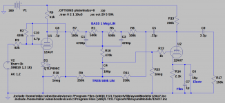
I suspect that grid stoppers on the 6N1Ps would be in order (at least on the final gain stage). Note: R27 and R28 represent a 500k log pot for volume control. The 4.7pF cap is probably unnecessary.

Attachments

Last edited:
- Status
- This old topic is closed. If you want to reopen this topic, contact a moderator using the "Report Post" button.
- Home
- Source & Line
- Analogue Source
- How about this phono idea