Are there any issues involved in putting (quality) attenuators in the line out of a phono pre amp ?
I ask this because my phono pre amp output has a bit too high of an output level .
I have also read conflicting opinions about if it will effect high frequencies.
I tend to believe it does not as it is no different than an amp's gain control .
I ask this because my phono pre amp output has a bit too high of an output level .
I have also read conflicting opinions about if it will effect high frequencies.
I tend to believe it does not as it is no different than an amp's gain control .
Last edited:
A pair of resistors forming a ladder is all you need.
Say 10k and 10k to ground, that will give you a
3dB loss, halving the signal and halving any noise.
No frequency degrading will happen.
Hi, to be specific that will give you - 6dB, rgds, sreten.
Are not all inline (RCA) attenuators just resistors? .
I prefer not modify any components if a simple inline attenuator will do.
Yes, but they are a network of two resistors configured as a divider and not just a single resistor in series.
A pair of resistors forming a ladder is all you need. Say 10k and 10k to ground, that will give you a 3dB loss, halving the signal and halving any noise.
No frequency degrading will happen.
Two resistors of same size will do 6dB, not 3 (half the output).
Degradation of the highest frequencies may happen if the load
capacitance is high at the output.
Yes,an "inline attenuator" will do, better connect this at the line input.
I ask this because my phono pre amp output has a bit too high of an output level .
Don't understand the bit too high outputlevel issue...
What do you need attenuate for?

Don't understand the bit too high outputlevel issue...
What do you need attenuate for?
what do you not understand about that?
Actually, it not "too high" .
It's just that what I got it input into would be a bit happier with a slightly lower input.
Last edited:
Are there any issues involved in putting (quality) attenuators in the line out of a phono pre amp ?
Yes - you don't want to raise the output impedance too high or you'll create HF roll-off in conjunction with the cable capacitance as well as increase your noise susceptibility. You don't want to go too low or dynamics of the source will start to suffer.
Better to use a step down transformer.
Quote:
Originally Posted by GDO View Post
Don't understand the bit too high outputlevel issue...
What do you need attenuate for?
Well, *you* wrotewhat do you not understand about that?
Actually, it not "too high" .
It's just that what I got it input into would be a bit happier with a slightly lower input.
Am I missing something?I ask this because my phono pre amp output has a bit too high of an output level .
When all is said an done.....
I just asked a simple question.
Such is life on a forum
Are you happy with the answer/s or are you still not sure how to best proceed ?
Not a bad idea. It also helps others researching this kind of thing.
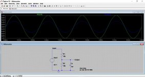
Here we have R1 and R2 forming the attenuator. The output is 50% of the applied input voltage as we are using equal values for resistive components of the attenuator.
Cx is the unknown cable capacitance and input capacitance of whatever we connect the attenuator to. Typically this could be around 100pF to a worst case of perhaps 470pF or even 1nF.
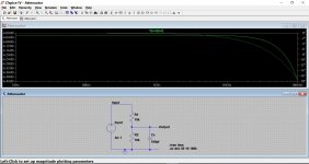
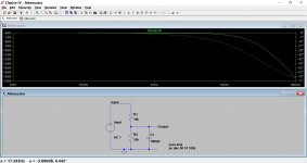
So here we can see the effect of 100pf loading followed by 1nf (1000pf). Even here, the response is only 1.5db down at 20kHz.
The output impedance is 5k. In other words, if we load the output by 5k then our output voltage now becomes one quarter of the applied input voltage (-12db)
On a practical note... guessing the attenuation factor needed is impossible. Far better to initially make the lower resistor variable and get the level you are looking for. Then take the variable pot out and measure it and fit a fixed resistor in its place.
Here we have R1 and R2 forming the attenuator. The output is 50% of the applied input voltage as we are using equal values for resistive components of the attenuator.
Cx is the unknown cable capacitance and input capacitance of whatever we connect the attenuator to. Typically this could be around 100pF to a worst case of perhaps 470pF or even 1nF.
So here we can see the effect of 100pf loading followed by 1nf (1000pf). Even here, the response is only 1.5db down at 20kHz.
The output impedance is 5k. In other words, if we load the output by 5k then our output voltage now becomes one quarter of the applied input voltage (-12db)
On a practical note... guessing the attenuation factor needed is impossible. Far better to initially make the lower resistor variable and get the level you are looking for. Then take the variable pot out and measure it and fit a fixed resistor in its place.
Attachments
- Status
- This old topic is closed. If you want to reopen this topic, contact a moderator using the "Report Post" button.
- Home
- Source & Line
- Analogue Source
- Attenuators after a phono pre amp?