So, I've trimmed DC offset on one of the TA2022 V1.2 from LJM.
Time to trim the second, and I see very light smoke starting to come from somewhere, I turn it off.
Upon examining the board I noticed this(see pic).
It's the pre-soldered resistor. The kit comes with a diode and a resistor already soldered in.
From the color bands it's a 200R 5% resistor.
I can just swap it for a 1% 2W metalfilm, but what could cause the resistor to get swollen(and surely burn had I not been quick to turn power off)?
I would rather not just replace the resistor and have some underlaying problem cause the amp to fail later, maybe taking my dipole woofers with it.
Attachments
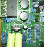
That first band looks orange (300) on my screen rather than red (200).
Have you measured it ? Just because it smoked, it doesn't mean it has failed. I'm not familiar with the amp or the TA2022 chip but if you can identify where it connects on the board then you might be able to match it to one on the application sheet for the chip (which has some 250 ohms).
Have you measured it ? Just because it smoked, it doesn't mean it has failed. I'm not familiar with the amp or the TA2022 chip but if you can identify where it connects on the board then you might be able to match it to one on the application sheet for the chip (which has some 250 ohms).
That first band looks orange (300) on my screen rather than red (200).
Have you measured it ? Just because it smoked, it doesn't mean it has failed. I'm not familiar with the amp or the TA2022 chip but if you can identify where it connects on the board then you might be able to match it to one on the application sheet for the chip (which has some 250 ohms).
You are absolutely right, I read in one thread about a 200R in that position. But it does measure 300R (in circuit).
I'll have a closer look at the PCB and see where that resistor connects.
Thank you
")
But it does measure 300R (in circuit).
It looks like 300 ohm from the picture. Its going to be OK then (at least at the moment
)It is between pos rail and 7805 input pin.
That sounds like additional circuitry that its supplying. The TA2022 data sheet doesn't show anything beyond the chip itself. So that's no help.
I would do a basic check of the working voltages. Make sure the 7805 is out-putting a correct 5 volts. You could also measure the voltage at each end of the resistor and so calculate the current and power dissipated. Is the applied voltage to the board within limits ?
Beyond that and you probably need a circuit to see what is going on.
It looks like 300 ohm from the picture. Its going to be OK then (at least at the moment
That sounds like additional circuitry that its supplying. The TA2022 data sheet doesn't show anything beyond the chip itself. So that's no help.
I would do a basic check of the working voltages. Make sure the 7805 is out-putting a correct 5 volts. You could also measure the voltage at each end of the resistor and so calculate the current and power dissipated. Is the applied voltage to the board within limits ?
Beyond that and you probably need a circuit to see what is going on.
I'll have a look at this tomorrow.
My brain is completely fried now. From experience, I should not go near electronics in this state lol
Thanks
Swapped the 300R for 4x 1K2 in parallel.
Then I tried powering on the amp again.
Faint smoke from the same area, turned it off again and swapped the 7805 for a new one.
While at it I set both trimpots to the midpoint, something I forgot when populating the board.
Powered it on again.
I've only had the guts to keep it powered on for about 30s at a time.
DC offset is 0.00 to 0.01 mVdc.
I don't trust those numbers though, if it seems too good to be true etc...
And does it all work OK now. Sound but no smoke ?
I have not yet tested it with my woofers.
No smoke, so far atleast.
A bit nervous about testing it with my woofers.
But I don't know if I can leave it on for an hour or so (without load) to test that it is stable before I hook it up.
All a bit strange isn't it. You could try a 1ohm 0.25 watt or 0.5 watt in series with the speakers as a test. That should protect them against anything odd going on and at some point you have to try it for real.
Yes, maybe a bad 7805 from the beginning?
Don't know if that could cause the voltage drop resistor to blow through?
It didn't blow, but it would given a few more seconds.
The 4x 1K2 are 0.6W so there is now "a" 300R 2.4W there.
The thinking with the series resistors to the woofers is that they'll blow before the woofers gets damaged?
I've been cautious with the choise of fuse as well, 400mA slow blow. The softstart (SST01 from P-A) keeps it from blowing at power up. It should blow fast enough if there's a problem I hope.
230V mains, 400VA toroidal transformer and two TA2022 boards.
78 type regs do fail for sure although if it was just the reg then I would expect it to both generate heat and for the output voltage to be incorrect.
Actually, and seeing as you mention fuses, well a series speaker fuse would be as good as anything.
There's not much you can do now beside test it thoroughly.
Actually, and seeing as you mention fuses, well a series speaker fuse would be as good as anything.
There's not much you can do now beside test it thoroughly.
Don't remember if I wrote that or not, rails are +/-30.4Vdc from the 0-22vac 0-22vac 400VA toroid transformer IIRC.
Going to leave it on for a minute or so today to see if DC offset on the previously faulty, hopefully, board is stable and that nothing starts smoking during that time.
Any idea of a good fuse value for a speaker protection fuse while testing the board?
Going to leave it on for a minute or so today to see if DC offset on the previously faulty, hopefully, board is stable and that nothing starts smoking during that time.
Any idea of a good fuse value for a speaker protection fuse while testing the board?
If you just want it playing at low volume then a 100ma fast blow is OK but anything fast blow up to 500ma or so will protect a large speaker.
Thanks
The woofers are Dayton 15" IB in open baffle
Product Specifications
Nominal Diameter15"
Power Handling (RMS)350 Watts
Power Handling (max)700 Watts
Impedance8 ohms
Frequency Response20 to 500 Hz
Sensitivity88.2 dB 1W/1m
Voice Coil Diameter2"
Magnet Weight90 oz.
Thiele-Small Parameters
Resonant Frequency (Fs)21.5 Hz
DC Resistance (Re)5.2 ohms
Voice Coil Inductance (Le)3.08 mH
Mechanical Q (Qms)8.92
Electromagnetic Q (Qes)0.63
Total Q (Qts)0.59
Compliance Equivalent Volume (Vas)8.79 ft.³
Mechanical Compliance of Suspension (Cms)0.26 mm/N
BL Product (BL)15.46 Tm
Diaphragm Mass Inc. Airload (Mms)207g
Maximum Linear Excursion (Xmax)14.3 mm
Surface Area of Cone (Sd)819.4 cm²
Yes, its a 'tough' speaker that will stand abuse, no doubt about that, but DC faults can be cruel.
So your rails are around 30 volts DC. Into 3 ohm (lets be realistic and say 3 ohms DC resistance even though they are 8 ohms nominal impedance) and that is still 'only' 300 watts dissipation. Could your speaker survive that. Not a chance. The cone would hit the end stops and the coil would melt/and/or/melt into the former.
A 100ma fuse will limit the dissipation to around 30 milliwatts and yet still allow you to play the speaker at a fair volume with music. A 0.5 amp fuse would limit at around 0.75 watt. Both assuming around 3 ohms DC resistance. If the resistance were nearer 8 ohm then the first example would be easier on the speaker at around 100+ watts (but still destructive), while the second example with the fuses would be worse at around 80 milliwatts and 2 watts respectively for a 0.1 and 0.5 amp fuse.
So a small fast fuse is a good option for speaker protection. You'll be surprised just how loud you can go before it blows too.
Yes, its a 'tough' speaker that will stand abuse, no doubt about that, but DC faults can be cruel.
So your rails are around 30 volts DC. Into 3 ohm (lets be realistic and say 3 ohms DC resistance even though they are 8 ohms nominal impedance) and that is still 'only' 300 watts dissipation. Could your speaker survive that. Not a chance. The cone would hit the end stops and the coil would melt/and/or/melt into the former.
A 100ma fuse will limit the dissipation to around 30 milliwatts and yet still allow you to play the speaker at a fair volume with music. A 0.5 amp fuse would limit at around 0.75 watt. Both assuming around 3 ohms DC resistance. If the resistance were nearer 8 ohm then the first example would be easier on the speaker at around 100+ watts (but still destructive), while the second example with the fuses would be worse at around 80 milliwatts and 2 watts respectively for a 0.1 and 0.5 amp fuse.
So a small fast fuse is a good option for speaker protection. You'll be surprised just how loud you can go before it blows too.
Thank you very much
It would cost a pretty penny getting new woofers shipped across the atlantic.
I'll try with a small fast blow, I think I have more or less every value up to 1A.
Don't know if I'll do it today though, my chronic pain is really bad after clearing some stuff out of the apartement. My fiance is 16 weeks pregnant and we're clearing out stuff to make room(for the baby, not her...she's barely showing lol).
It would cost a pretty penny getting new woofers shipped across the atlantic.
Aye, you don't want to be doing that. Sorry to hear about the pain
but congrats on the baby You'll have to crack on with the diy stuff while you still have the chance.Aye, you don't want to be doing that. Sorry to hear about the pain
Thanks
Yeah, kind of what I figured as well. Better get as many as possible of my projects done before he/she is born.
Time etc will be kind of limited after that.
Hooked up the second board again. The one I know to work.
I had it trimmed to well under +/-5mVdc. In BTL it's around 80-90mVdc.
I noticed that I could clearly hear the relay on that board..so that means the relay on the other doesn't work or the circuit driving it doesn't work.
I had it trimmed to well under +/-5mVdc. In BTL it's around 80-90mVdc.
I noticed that I could clearly hear the relay on that board..so that means the relay on the other doesn't work or the circuit driving it doesn't work.
- Status
- This old topic is closed. If you want to reopen this topic, contact a moderator using the "Report Post" button.
- Home
- Amplifiers
- Class D
- TA2022 LJM swollen resistor, why?