In the email-bag this morning, an application note from Linear Technology which details an improved measurement setup capable of very low noise measurement. Follows on the work of Jim Williams, et. al.
Interesting that we all use cookie tins -- theirs has an additional mu-Metal box.
http://cds.linear.com/docs/en/application-note/an159fa.pdf
JW
Interesting that we all use cookie tins -- theirs has an additional mu-Metal box.
http://cds.linear.com/docs/en/application-note/an159fa.pdf
JW
Quoted from the article:
"A simple steel enclosure would require extremely
thick walls (estimates are at least 1/2" wall thickness) in
order to provide adequate shielding. This would require
a custom steel box welded together, one that would most
likely never move once placed on a bench due to the
weight involved."
and
" If you do not have an issue with creating your own enclosure,
sheets of Mu Metal are available for purchase for
cutting and forming to custom shapes. Thicker sheets are
recommended for best shielding to avoid saturation of the
material and magnetic field incursion. Be aware that the
relative magnetic permeability will drop during forming
and the material must be properly annealed afterwards
in a hydrogen-rich atmosphere."
This is some serious DIYing for a proper enclosure. Do not get fooled by cookie box.
You can obtain muShield samples (you have to pay) from the company MuShield Magnetic Shielding - Sample Kits
You have to take care not to crease or bend the material as it drops the permeability quite quickly.
THAT transistors are BJT, not JFET. Samuel has an article on a very low noise amplifier in LA#3 using multiple BF862.
For measuring noise, why didn't the authors use cross-correlation with something like an SR785 or Agilent/Keysight?
Lastly -- you can use a spectrum analyzer with table sweep and skip 60Hz and 120Hz (50Hz and 100Hz) in the lookup table.
Last edited:
Thanks Jack
filed/saved under "testing for ripple rejection of linear regs."
I think the greatest take away from this app note for system design* is keep input bypass away from the linear regulator! note decoupling ferrite bead.
*designs using linear regs to clean up switching ripple and hash
again my pet peeve for audio guys adding mega caps on switching supplies outputs = it wont make things better often worse.
I would of liked to see the Jim Williams driver regulator board in photos for injecting the input ripple on DC>
also interesting grounding between the driver and DUT not sure if systems have all that luxury.
Last edited:
... I think the greatest take away from this app note for system design* is keep input bypass away from the linear regulator!
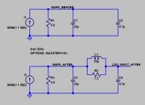
I suspect that decision was driven by the authors' unwillingness to spin yet another revision of the PCB design. A better way to skin the cat is to introduce a big ole bohunker impedance in the dotted line current loop of Fig 21, which attenuates the current at 500 kHz but has no effect at DC. I suggest the L1-R2 network shown in the schematic below. You can calculate its impedance at 500 kHz and compare that against the impedance of the 4.7uF bypass capacitor right at the linear regulator input terminal.
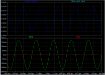
The L1-R2 network greatly attenuates ripple at the input to the linear voltage regulator (top panel) AND it greatly reduces the current flowing in C4 -- the dotted line current loop shown in Figure 21 of the Application Note. (bottom panel)
Choosing R2 is a tradeoff between attenuation and damping; the 7.5R shown here is just slightly underdamped (zeta < 1). Other designers are of course free to choose their own point on the tradeoff spectrum.
_
Attachments
silly , I tend to believe the brain power and pocket books of industry trounces one academic with free spice tools.I suspect that decision was driven by the authors' unwillingness to spin yet another revision of the PCB design.
Count the number of board spins and total do-overs they admit to, in the four articles. That's a lower bound on the number of board spins they actually performed. Do-overs grind down your enthusiasm and sap your energy.
I don't think they ran out of money or out of cleverness, I think they were simply exhausted. This was article #4 of 4 in the series for EDN-Europe magazine (link), they just wanted the whole project to be DONE, their boss just wanted it DONE. So, I imagine, they did the expedient thing which saved time and saved a board rev. Anybody can see that attenuating the dotted line current in Fig 21, would solve the problem. The authors just attenuated it in the kludgiest way possible - by removing the capacitor.
I don't think they ran out of money or out of cleverness, I think they were simply exhausted. This was article #4 of 4 in the series for EDN-Europe magazine (link), they just wanted the whole project to be DONE, their boss just wanted it DONE. So, I imagine, they did the expedient thing which saved time and saved a board rev. Anybody can see that attenuating the dotted line current in Fig 21, would solve the problem. The authors just attenuated it in the kludgiest way possible - by removing the capacitor.
Last edited:
Don't forget the end goal is matching the device data sheet performance ,
one could easily rearrange the PCB tracks adding your power line filter with out a having pretty board. besides all the testing is made up from at least what, 3 custom boards? so what board you speak of is unclear. They 1st find the measurement noise floor so they know how much ripple to inject on the regulators input, If they added a power line filter they would be attenuating the input ripple reaching the DUT, so it doesn't make any sense to do that for these tests. PS Interesting you have some imagination for far reaching story telling of things. it's plain silly guessing and reading between the lines.
homework >model the ripple source amp and you'll see clearly what problems larger bypass caps pose, let alone putting a higher fraction of the total on a LN ground system.
Last edited:
Quoted from the article:
"A simple steel enclosure would require extremely
thick walls (estimates are at least 1/2" wall thickness) in
order to provide adequate shielding. This would require
a custom steel box welded together, one that would most
likely never move once placed on a bench due to the
weight involved."
and
" If you do not have an issue with creating your own enclosure,
sheets of Mu Metal are available for purchase for
cutting and forming to custom shapes. Thicker sheets are
recommended for best shielding to avoid saturation of the
material and magnetic field incursion. Be aware that the
relative magnetic permeability will drop during forming
and the material must be properly annealed afterwards
in a hydrogen-rich atmosphere."
This is some serious DIYing for a proper enclosure. Do not get fooled by cookie box.
The steel enclosure wouldn't be too hard to make, it would be heavy though.
But hey, people use 300VA trafos all the time, sometimes in doubles - so what's a bit of weight here and there got to do with it anyway?
you could do fine much lighter - they even mention the idea - just use air space nested magnetic shielding boxes - much lighter gage low carbon steel shields would be fine
air has huge magnetic reluctance
I designed, debugged, verified strain gage amps with gain up to 8000 without any mu metal - just 16 gage steel boxes
it also helps to understand, use loop minimizing wiring, trace in the box, on the PCB - its easy to miss out on another order of magnitude magnetic field coupling rejection right there
I would never try single-ended external wiring at those levels either - shielded diff pair or even shielded star quad, but I never needed MHz bandwidth
Last edited:
you could do fine much lighter - they even mention the idea - just use air space nested magnetic shielding boxes - much lighter gage low carbon steel shields would be fine
Matryoshka doll cookie tins? Quite possibly -- an Oreo cookie container easily fits into a Danish Christmas Cookie container.
To their credit, muShield state "try something cheaper first".
Pomona makes it easy to create your own short, balanced shielded cables.
Can you explain some detailed-ish examples of good practice please.....It also helps to understand, use loop minimizing wiring, trace in the box, on the PCB - its easy to miss out on another order of magnitude magnetic field coupling rejection right there.
Thanks. Dan.
Just for youThe best way to control conducted spikes is through the
use of ferrite beads on the input of the regulator.
In answer to loops, 0V return plane (Ground plane) for most signals... Rout critical loops first with the smallest possible trace lengths, use copper pours where possible for power, but not to much, just the right amount, to much is bad.
AC mains signals and similar Bus bar routing...
DC power out Bus bar routing or use a plane as above.
Last edited:
- Status
- This old topic is closed. If you want to reopen this topic, contact a moderator using the "Report Post" button.
- Home
- Design & Build
- Equipment & Tools
- 2nV/Rt Hz Noise Measurement