Since I have a couple of headphones at home and I don't have any amplifier for them, I decided to build one. Of course I could buy one, but I doubt that I would be satisfied with it......
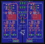
For the basis I took schematic from TI evaluation module for LME49600 with DC servo, which is nothing new. On the PCB pic below, you'll notice that I went for dual mono version PCB design. Each channel, VAS and buffer, has its own positive and negative low noise regulators. For the first time I used TPS7A4901 and TPS7A3001 regulators, so I don't know what to expect from them. I also still haven't done any calculations for various loads if these regulators will be sufficient, since positive one can supply 150mA and negative 200mA. I plan to supply the amplification part of the circuit with +/-10V.
Stay tuned for more.
Best Regards,
Aleš
Attachments
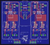
Aleš, why only 150/200mA LDOs if output buffers takes about 550mA when short-circuit? 150mA means about 5V on 32ohms headphones, without considering OPA2604 power consumption, right?
Also, the 2 x OPA2604 takes 20-30 mA each, so why not using old 78xx/79xx or your TPS7A47 regulators?
I built myself this headamp, but I was using LME49720+BUF634T heatsinked (BW-high) + LM317/337. I had no oscillations, no noise and no hum, but I'm sure with a decent PCB and better PSU performance could be increased. Gain used was about 5X and DC-output was around 1mV (depends mostly of VAS OPAMPs used).
If you'll have some spare PCBs sometimes, I'll probably buy a couple.
Thanks,
Raul.
Thank you guys!
I agree about those filtering caps. I will make more space between them.
Relay still isn't connected to anything as you can also see in the schematic. I'll probably just add power up delay, though there won't be any protectiton if DC fails...
Old regulators such as 78XX/79XX and LM3xx are not option in my case as I want to build something with good specs, otherwise I could just buy one HPA from China.
I used 150mA LDOs because I wanted to try them.The more I think about it, I'll probably change this to TPS7A4701 and TPS7A3301 as you suggested. With low current per rail I lose the versatility to use HPA with many different headphones.
Best Regards,
Aleš
Yep, looks very good. Are you sure the capacitors C25/C26 and C27/C28 aren't too close together though - that looks very tight?
/U.
PS: What powers the relay? Doesn't look like anything is connected")
I agree about those filtering caps. I will make more space between them.
Relay still isn't connected to anything as you can also see in the schematic. I'll probably just add power up delay, though there won't be any protectiton if DC fails...
Aleš, why only 150/200mA LDOs if output buffers takes about 550mA when short-circuit? 150mA means about 5V on 32ohms headphones, without considering OPA2604 power consumption, right?
Also, the 2 x OPA2604 takes 20-30 mA each, so why not using old 78xx/79xx or your TPS7A47 regulators?
I built myself this headamp, but I was using LME49720+BUF634T heatsinked (BW-high) + LM317/337. I had no oscillations, no noise and no hum, but I'm sure with a decent PCB and better PSU performance could be increased. Gain used was about 5X and DC-output was around 1mV (depends mostly of VAS OPAMPs used).
If you'll have some spare PCBs sometimes, I'll probably buy a couple.
Thanks,
Raul.
Old regulators such as 78XX/79XX and LM3xx are not option in my case as I want to build something with good specs, otherwise I could just buy one HPA from China.
I used 150mA LDOs because I wanted to try them.The more I think about it, I'll probably change this to TPS7A4701 and TPS7A3301 as you suggested. With low current per rail I lose the versatility to use HPA with many different headphones.
Best Regards,
Aleš
I'm just hoping will have some spare PCBs for this project; many of us we'd like to try it out.
Sure, why not. I can even solder you some of the tricky parts (QFN package
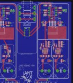
).I redid the right channel. Regulators are now TPS7A4701 and TPS7A3301... One down one to go
.BR,
Aleš
Attachments
Aleš, may I suggest a switch for gain adjustment?
A gain switch with 2 or 3 positions would be quite good if you intend to use this headamp with different sensitivity headphones; something like 1X/3X/6X should cover most headphones and will also deal with most analogue & digital sources as well (portable sources with an output of 1-1.5V RMS need a higher gain and home DACs & CDs having 2-2.3V RMS may need a lower gain).
A gain switch with 2 or 3 positions would be quite good if you intend to use this headamp with different sensitivity headphones; something like 1X/3X/6X should cover most headphones and will also deal with most analogue & digital sources as well (portable sources with an output of 1-1.5V RMS need a higher gain and home DACs & CDs having 2-2.3V RMS may need a lower gain).
mravlca - very nice layout work! I think your board is by far the best realization of that National datasheet circuit I've ever seen posted.
Suggestion: use an op amp with a lower input offset voltage for the servo than the one you are trying to correct. If the same op-amp is used for the servo the best you will do is that same op-amp's offset voltage on the output, which will be exactly the same result if you just looped a single op-amp of that type with the LME49600.
Consider the (also FET input) OPA140 (keeping it dual mono) or the OPA2140 for both for the servo chips. Those have a maximum offset of 120uV vs. the datasheet "typical" of 1mV or "max" of 5mV for the OPA2604. I've built a bunch of OPA140 + LME49600 boards (my O2 booster board project) and routinely measure DC output offsets in the 50uV or so range. No servo, just the OPA140 looped with the LME49600. Using it for the servo you should get similar results. The National circuit with the servo in your board here will definitely produce a more general purpose board than just looping only an op-amp and buffer. Op amps with high(er) input offset votlage but better THD+N specs can be used for the "audio" (non-servo) op-amp.
A good alternative to the "DC precision" chips like the OAP140/OPA827/OPA627 for the servo op-amp is a chopper-stabilized "zero" DC offset op-amp, followed by a filter.
If you should decide to use separate servo chips with lower offset specs I would also be interested in buying a couple of boards! I've never messed with those regulator chips before (they look good on paper!) or tried to solder them. It would be interesting.
Suggestion: use an op amp with a lower input offset voltage for the servo than the one you are trying to correct. If the same op-amp is used for the servo the best you will do is that same op-amp's offset voltage on the output, which will be exactly the same result if you just looped a single op-amp of that type with the LME49600.
Consider the (also FET input) OPA140 (keeping it dual mono) or the OPA2140 for both for the servo chips. Those have a maximum offset of 120uV vs. the datasheet "typical" of 1mV or "max" of 5mV for the OPA2604. I've built a bunch of OPA140 + LME49600 boards (my O2 booster board project) and routinely measure DC output offsets in the 50uV or so range. No servo, just the OPA140 looped with the LME49600. Using it for the servo you should get similar results. The National circuit with the servo in your board here will definitely produce a more general purpose board than just looping only an op-amp and buffer. Op amps with high(er) input offset votlage but better THD+N specs can be used for the "audio" (non-servo) op-amp.
A good alternative to the "DC precision" chips like the OAP140/OPA827/OPA627 for the servo op-amp is a chopper-stabilized "zero" DC offset op-amp, followed by a filter.
If you should decide to use separate servo chips with lower offset specs I would also be interested in buying a couple of boards!
I've never messed with those regulator chips before (they look good on paper!) or tried to solder them. It would be interesting.
Last edited:
mravlca great job on the regulators, these can output 1A vs the 330mA of the TPS7A4901. Are you planning to use +/-15V rails ? Also are you planning to do this with the OPA2604 or the LME49720NA ? Should the BW pin of LME49600 be connected to pin 3 ?
+/-12V or +/-15V, it will be configurable via regulators resistors. OPA2604 is in the schematic because I used library from eagle and didn't change it afterwards.
What are the advantages of the BW pin shorted in the audio band?
Aleš, may I suggest a switch for gain adjustment?
A gain switch with 2 or 3 positions would be quite good if you intend to use this headamp with different sensitivity headphones; something like 1X/3X/6X should cover most headphones and will also deal with most analogue & digital sources as well (portable sources with an output of 1-1.5V RMS need a higher gain and home DACs & CDs having 2-2.3V RMS may need a lower gain).
You may
and I will integrate this on to the PCB.mravlca - very nice layout work! I think your board is by far the best realization of that National datasheet circuit I've ever seen posted.
Suggestion: use an op amp with a lower input offset voltage for the servo than the one you are trying to correct. If the same op-amp is used for the servo the best you will do is that same op-amp's offset voltage on the output, which will be exactly the same result if you just looped a single op-amp of that type with the LME49600.
Consider the (also FET input) OPA140 (keeping it dual mono) or the OPA2140 for both for the servo chips. Those have a maximum offset of 120uV vs. the datasheet "typical" of 1mV or "max" of 5mV for the OPA2604. I've built a bunch of OPA140 + LME49600 boards (my O2 booster board project) and routinely measure DC output offsets in the 50uV or so range. No servo, just the OPA140 looped with the LME49600. Using it for the servo you should get similar results. The National circuit with the servo in your board here will definitely produce a more general purpose board than just looping only an op-amp and buffer. Op amps with high(er) input offset votlage but better THD+N specs can be used for the "audio" (non-servo) op-amp.
A good alternative to the "DC precision" chips like the OAP140/OPA827/OPA627 for the servo op-amp is a chopper-stabilized "zero" DC offset op-amp, followed by a filter.
If you should decide to use separate servo chips with lower offset specs I would also be interested in buying a couple of boards!
Thank you agdr. As said before OPA2604 is in the scheamtic just because of the footprint and part. My intial plan was to use OPA602 in place for servo and OPA827 for VAS. In place of dual opamp I intend to use dual single opamp to dual opamp converter, which makes PCB smaller and easier to implement other parts. I also plan to make my own converter PCBs where DIP and SOIC packages will be possible.
Best Regards,
Aleš
What are the advantages of the BW pin shorted in the audio band?
You may
Hi Aleš,
I don't know with LM49600, but with BUF634T I had some oscillations without BW being shorted (homemade PCB), but after shorting the BW everything was fine. Besides quiescent current difference, LM49600 has a lower voltage noise density when BW is shorted (2.6 vs. 3 nV/√Hz at 10KHz) and a lower settling time (60ns vs 200ns) based on datasheet, in case it matters.
As for the gain, I believe you now have 3X fixed gain, but I was hoping there might be a way to integrate a small switch and 2 or 4 more resistors connected nearby R9, R11/R10, R12. Anyway, I'm so waiting for your first PCBs and first tests, no matter about fixed gain.
Thank you,
Raul.
Thank you Aleš for designing this!
As the PCB layout shows dual OPAMPs we need to use an excellent audio OPAMP with a very low offset input to handle the DC output. I very much trust the designer of M2Tech devices and he was using AD8599 (10uV offset) and AD8672 (75 uV offset) dual-OPAMPs in I/V, LPF and output stages as well. I had them both tested as audio OPAMPs only and the sound is quite neutral, clean, not grainy and non fatiguing. These are high-quality low noise OPAMPs and shouldn't require any additional bypassing, just DIP8 adapters perhaps.
Just my 2 cents: I must admit that I like the sound of very expensive MUSES 01/02/8820/8920 (typical offset between 0.3-0.5 mV) because I saw them driven till the max. output voltage and when starting to distort I saw on my scope a little rounded horizontal shape (with a bit of ripple on top) instead of a regular flat line on top of the signal, like other OPAMPs. Perhaps this is why some people like the sound of these OPAMPs, because when distorting the shape looks more like tubes then transistors. If I'll grab 1 of these PCBs I'll definitely give a try with a couple of MUSES I have on stock.
My intial plan was to use OPA602 in place for servo and OPA827 for VAS.
The OPA827 is a great chip for the audio path! I've used it before. Highly recommended.
After I did my post above it hit me that the "other" reason for a servo, to zero out input DC coming from a source in an amp with no blocking capacitors, would still be valid in National's circuit even if the same chip were used for the servo as for the audio path. In fact I'll bet that it the main purpose they had in mind since the circuit has no blocking caps.
I typically use a blocking cap in the circuit somewhere to block source DC. The only reason I consider servos anymore is for output offset reduction, especially to help eliminate drifts over time/temperature. The problem I've been concerend about with servos (for getting rid of input source DC) is response time. Depending on the part values the integrator can take a couple of seconds to settle, with some level of DC making it out to the headphones in the meantime.
At any rate, your board and circuit looks great!
Guys I really appreciate all your nice comments.
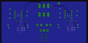
I think I am really close now, just delay circuit needs to be added and I'm actually done. I split the ground plane all the way to the output pads, where also are GND pads for input and GND for the Alps. Kind of star ground where grounds from left and right channel meet. P1 GND pad is for connecting metal part of the alps housing. By my experience pots can sometimes make hiss noise if they are not properly grounded.
Voltage that power rails will have is 12V. It is because I plan to use 47uF 16V 1206 MLCC capacitors on the outputs of the regulators. Another thing I am considering to do with regulators is to put resistors on the output of them. That way they would always have some load which would draw around 50mA of current per rail. Some say this helps the regulators so they are not so "slow". I will make place for these resistors, if there will be no benefit from them, they can easily be omitted.
On the bottom side of the PCB I placed smd DIP switch for gain. These can be accessed if there will be cutout in the bottom of the enclosure. I know it is not the best option, but at least there is.
Br,
Aleš
Attachments
This project looks so great Aleš, I really think it will beat up THE WIRE and most other similar amps in terms of noise and THD, especially because of your great layout design and very low noise LDOs used. I will anticipate that most reviewers will use words like "black background", "clean", "detailed" and "not grainy sound" and I'm sure they'll be right about it.
Though I was hoping for +/-15V, mostly because of max. power output (10-11V RMS instead of 7-8V RMS), but maybe your decision to go for +/-12V would be better because is less expensive and less heat generated. Who'll need more output power will DIY this by himself or will buy 2x PCBs and go balanced.
Regards,
Raul.
Hi Raul,
well I hope it will have better specs than The Wire, but you never know. Its layout is really good, especially because it has 4 layer PCB.
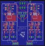
Anyway I am still working on my PCB, making final corrections. I changed bridge rectifier to diodes, where I will use SBYV27 (15ns) type.
I made simple delay circuit, but I will need to test it first on breaboard to see if it is working correctly.
Best Regards,
Aleš
well I hope it will have better specs than The Wire, but you never know. Its layout is really good, especially because it has 4 layer PCB.
Anyway I am still working on my PCB, making final corrections. I changed bridge rectifier to diodes, where I will use SBYV27 (15ns) type.
I made simple delay circuit, but I will need to test it first on breaboard to see if it is working correctly.
Best Regards,
Aleš
- Status
- This old topic is closed. If you want to reopen this topic, contact a moderator using the "Report Post" button.
- Home
- Amplifiers
- Headphone Systems
- Dual mono LME49600