Hi,
I have just completed the rebuild of my power amp. I have not really learnt how to measure a power amp and I don't have a 8R power resistor so I have basically left the output unloaded. Is that OK?
The following attached photos are:
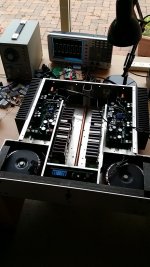
1) Test set up;
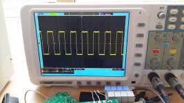
2) 10kHz square waves.
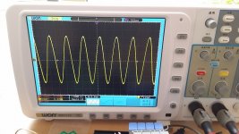
3) 100kHz sine waves.
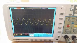
4) 1MHz sine waves.
Note that the input low pass filter is currently set to very high at 1.8MHz (195R, 470pF). The signal generator runs from a cheap step down transformer that is a bit noisy so the input signal is not 100% clean. Signal injection is at the RCA input of the amplifier. Output measurements are made at the speaker terminals after the inductor.
Earlier tests found bad overshoot at square waves. I then increased the phase lead capacitor at the feedback path from 18pF to 68pF and it is now overdone. I think 61pF would be perfect but I can't find such a value. With 56pF there is a slight overshoot. But does it matter?
I have just completed the rebuild of my power amp. I have not really learnt how to measure a power amp and I don't have a 8R power resistor so I have basically left the output unloaded. Is that OK?
The following attached photos are:
1) Test set up;
2) 10kHz square waves.
3) 100kHz sine waves.
4) 1MHz sine waves.
Note that the input low pass filter is currently set to very high at 1.8MHz (195R, 470pF). The signal generator runs from a cheap step down transformer that is a bit noisy so the input signal is not 100% clean. Signal injection is at the RCA input of the amplifier. Output measurements are made at the speaker terminals after the inductor.
Earlier tests found bad overshoot at square waves. I then increased the phase lead capacitor at the feedback path from 18pF to 68pF and it is now overdone. I think 61pF would be perfect but I can't find such a value. With 56pF there is a slight overshoot. But does it matter?
Attachments
I tried to hear the difference. I suspect I heard none.
What I heard a dramatic difference was the output LMOSFET bias current. Yesterday I spent many hours changing bit by bit trying to find the optimal sound.
Manufacturers' tech note and most designers recommend setting bias current to be 100mA+. I prefer 45mA to 50mA. To my ears it gives me much cleaner sound.
Last edited:
I set the bias current by ears. Is there a way I can see the crossover distortion from my oscilloscope? I tried a larger signal at 10kHz and magnify it on the screen at 0V crossing and could not find any "teeth". Perhaps I shouldn't look at the 0V crossing alone but need to look up or down the sine wave?
You need more tools.
Definitely a test load. You can divvy something up with a low value resistor and a halogen light bulb. Check that the cold resistance isn't too low.
You can sort of see the level of XO distortion and the XO width by monitoring one of the nodes around the VAS. When monitoring with the correct scope sync in place and the amplifier playing sine into a load adjust the bias and you will see which components correlate with the crossover.
You might also be able to bring it out using this test method:
http://www.ti.com/lit/an/snaa047a/snaa047a.pdf
ED- by the way, I've found DSO's mask a lot of information compared to the good old analogue types, and things that are obvious on analogue at the same zoom on a DSO won't be so. So if you have an analogue laying around definitely run a couple of probes around with that to compare.
Last edited:
Found one of the two 2SJ162 runs 3 degree higher in temperature after playing music for 3 hours. Since manufacturer's tech note says no LMOSFET source resistors are needed, and most designers here said source resistors are necessary, I went half away. I used 0.1R source resistors.
Would 3 degree higher temperature on one of the two LMOSFETs worry you?
Also, after the amplifier was turned off, the negative rail reaches 0V earlier than the positive rail, on which it stays 2.5V for a long time.
Other than those 2, I have not found any other concerns. DC offsets are 1mV and 0mV respectively (with no component matching done). There are no turn on thumps, turn off thumps. The VAS transistors run to 45 degrees. The LMOSFETs run to 39 degrees. All other components run cooler than those.
yes, crossover is almost hidden when there is no output current............... do you mean if there is no load the crossover distortion won't show up?
Connect a low resistance load to see crossover, on a scope trace.
Try a resistance equal to your rated impedance for the output stage.
Every power amplifier should easily be able to drive a half resistance load for a few seconds and maybe for a minute or two.
eg for a 4ohms rated amplifier try using a 4r0 test load for longer term testing and try a 2r0 test load for a short time, keep the heatsink cool but using a low duty cycle (10seconds on and 60seconds off).
Here's a comment on THD testing I found in this forum. I've never tried it.
Apologies, I don't know the author.
"THD analyzer is best. If distortion is high enough to become visible on a scope, it's definitely far above the audibility threshold.
Depending on the sharpness of the scope trace, distortion doesn't become visible until it's about 1 or 2 percent. you can approximate a medium sensitivity THD analyzer by using a dual trace scope, using the ch1 & ch2 add function, with ch2 inverted (it's now subtracting) and monitoring the input signal to ch1, and monitoring the output on ch2, and adjust for the smallest waveform".
Brian.
Hi,
I have just completed the rebuild of my power amp. I have not really learnt how to measure a power amp and I don't have a 8R power resistor so I have basically left the output unloaded. Is that OK?
The following attached photos are:
1) Test set up;
2) 10kHz square waves.
3) 100kHz sine waves.
4) 1MHz sine waves.
Note that the input low pass filter is currently set to very high at 1.8MHz (195R, 470pF). The signal generator runs from a cheap step down transformer that is a bit noisy so the input signal is not 100% clean. Signal injection is at the RCA input of the amplifier. Output measurements are made at the speaker terminals after the inductor.
Earlier tests found bad overshoot at square waves. I then increased the phase lead capacitor at the feedback path from 18pF to 68pF and it is now overdone. I think 61pF would be perfect but I can't find such a value. With 56pF there is a slight overshoot. But does it matter?
Looks pretty good to me. The 100kHz fundamental looks undistorted, and even the higher freq fundamental looks intact. Of course the higher harmonics in the square are not reproduced so the output starts to look like a sine as you go up in frequency. Naturally the level has gone down by then.
BUT - big caveat: how does the input signal look? You mentioned the step down transformer, that certainly does not have unlimited bandwidth. You should look at both input and output and see if you can construct the difference with your scope. That would give you the true amplifier response.
Jan
Would 3 degree higher temperature on one of the two LMOSFETs worry you?
The 3 degrees can easily come form non-uniform air flow on the heatsink. Anything can cause that, depending on how you set it on a rack/table, what's next/below/near it. Don't worry about 3 degrees.
Jan
Thanks, Jan.
I have compared the input and output. There are some tiny hairs when I measured the square waves at 10kHz straight out of the signal generator, which also showed up in the amp output. But other than those, the curves appear to be very clean. When I took the first 2 photos I forgot to select "single" so it was on "autoset" continuous refreshing mode. I used "single" when I took the photo of the 1MHz so that curve appears to be even cleaner. No ringing was found on the square waves. Not sure if that is still the same after adding some load.
I have compared the input and output. There are some tiny hairs when I measured the square waves at 10kHz straight out of the signal generator, which also showed up in the amp output. But other than those, the curves appear to be very clean. When I took the first 2 photos I forgot to select "single" so it was on "autoset" continuous refreshing mode. I used "single" when I took the photo of the 1MHz so that curve appears to be even cleaner. No ringing was found on the square waves. Not sure if that is still the same after adding some load.
Tony, if you are still here.
Did you use those power transistors without issues?
I have simulated that for a 1V input signal, with my amplifier a 8R load will dissipate 87W on the power transistor. The largest power resistor from Wagner is 100W. 87W is very close to the rating. It is going to be very hot! it can cook an egg in an couple of minutes. If I mount it on plastic case it may melt it. If I mount it on a piece of timber it may start a fire on it?
Perhaps I should use maximum 0.5V input.
Last edited:
Thanks, Jan.
I have compared the input and output. There are some tiny hairs when I measured the square waves at 10kHz straight out of the signal generator, which also showed up in the amp output. But other than those, the curves appear to be very clean. When I took the first 2 photos I forgot to select "single" so it was on "autoset" continuous refreshing mode. I used "single" when I took the photo of the 1MHz so that curve appears to be even cleaner. No ringing was found on the square waves. Not sure if that is still the same after adding some load.
Yes you should definitely test with load. The performance without load may be of academic interest but of little practical value.
jan
Bill, a cheap dummy load can be made like this:
It can handle 150W for a while and is as non-inductive as it needs to be for your amps. If you need to run it for some time at some intermediate level, use a desk fan to cool it.
You could observe the clipping behaviour and see if there is any rail sticking etc.
Set a true RMS DMM on AC and with a 50Hz test tone measure voltage across the load. Connect scope to both ends of load to observe clipping.
You could make one easily with fourteen 2R2 10W wirewounds (zinc plated nails are easy to solder), or just drop in and borrow that one. You have my address. It has soldered-on leads and spade lugs. Apparently the so-called "non-inductive" wirewounds are just relablelled ordinary wirewounds in most cases.
An externally hosted image should be here but it was not working when we last tested it.
It can handle 150W for a while and is as non-inductive as it needs to be for your amps. If you need to run it for some time at some intermediate level, use a desk fan to cool it.
You could observe the clipping behaviour and see if there is any rail sticking etc.
Set a true RMS DMM on AC and with a 50Hz test tone measure voltage across the load. Connect scope to both ends of load to observe clipping.
You could make one easily with fourteen 2R2 10W wirewounds (zinc plated nails are easy to solder), or just drop in and borrow that one. You have my address. It has soldered-on leads and spade lugs. Apparently the so-called "non-inductive" wirewounds are just relablelled ordinary wirewounds in most cases.
")
- Status
- This old topic is closed. If you want to reopen this topic, contact a moderator using the "Report Post" button.
- Home
- Amplifiers
- Solid State
- Power Amp Measurements - Do these look good?