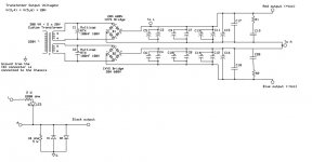
The 7815 input pin should connect to "Red output", it's ground to "A", and the output should be +15V measured to "A".
The 7915 input pin should connect to "Blue output", it's ground to "A", and the output should be -15V measured to "A" (meter's black probe to "A", red to the 7915 output).
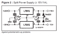
Don't forget to notice that the pin configuration of the two regulators is not the same, the 7915 ground pin is not in the middle as it is for the 7815.
The 7915 input pin should connect to "Blue output", it's ground to "A", and the output should be -15V measured to "A" (meter's black probe to "A", red to the 7915 output).
Don't forget to notice that the pin configuration of the two regulators is not the same, the 7915 ground pin is not in the middle as it is for the 7815.
I seem to remember Andrew mentioning a while back that some 79 regs need a minimum load of a few milliamps.
Also consider adding diodes (reverse polarity) between each 15 volt reg output and ground and across each reg to prevent a reverse bias situation if the rails rise at slightly different rates. That can cause a latch up on switch on.
Also consider adding diodes (reverse polarity) between each 15 volt reg output and ground and across each reg to prevent a reverse bias situation if the rails rise at slightly different rates. That can cause a latch up on switch on.
Hush,
looks like D1 & D2 need to be able to pass Fault Current to Chassis.
anrew, I did not asemble that part, should I?
Hi Hushang,
What are the voltages you measure before and after the regulators, in each of the two cases (7815 connected and disconnected) ?
Do you only have the regulators, or any extra hardware ?
What's the load in the regulators ?
tnx alot, without regs i have +/- 34 volts, this ps also have +-34 v output, when i connect both regs +34 and +15 works but other not, why is that so?
What I meant was:
Situation 1: Both Regulators there
Input Voltage of 7815 = ??
Output Voltage of 7815 = ??
Input Voltage of 7915 = ??
Output Voltage of 7915 = ??
Situation 2: 7815 removed
Voltage at Red output = ??
Input Voltage of 7915 = ??
Output Voltage of 7915 = ??
All these voltages measured with respect to node 'A', of course
Sorry if I dare...
somebody already said it:
you did pay attention to the fact that 78xx and 79xx have a different pinout, right?
78xx has 1=IN, 2=GND, 3=OUT
79xx has 1=GND, 2=IN, 3=OUT
Did you also put the input and output caps caps?
(edit: I just saw your latest post, taht came while I was typing...)
In case there is a heatsink, remember that the tab of the TO-220 package is connected to the center pin. If the two regulators share the heatsink, you want the tabs to be insulated from the heatsink, otherwise the IN of 7915 goes to ground...
Really, don't get mad if I recall thee basics and you had already done it properly
-
Last edited:
input 7915 about -36 too
The absolute maximum rating for 7915 input voltage is -35V
Sorry if I dare...
somebody already said it:
you did pay attention to the fact that 78xx and 79xx have a different pinout, right?
78xx has 1=IN, 2=GND, 3=OUT
79xx has 1=GND, 2=IN, 3=OUT
Did you also put the input and output caps caps?
(edit: I just saw your latest post, taht came while I was typing...)
In case there is a heatsink, remember that the tab of the TO-220 package is connected to the center pin. If the two regulators share the heatsink, you want the tabs to be insulated from the heatsink, otherwise the IN of 7915 goes to ground...
Really, don't get mad if I recall thee basics and you had already done it properly
-
bro your right, :d ,tnx so much bro it was heatsink, didnt know that,
(F) omg tnx alot
tow days i'm thinking checking... tnx alot (F)

this is your Main Audio Ground to Chassis connection.is it better to use "d1,d2 and r10 ohm 5w" part for chasis?
It can be used to reduce hum.
It can also be used with a bypass switch to short out the components, i.e. switchable between Disconnecting Network and direct zero ohms.
Or you can make a direct wire link from Main Audio Ground to Chassis.
BUT:
This link may have to pass Fault Current until the Mains fuse ruptures.
That Fault Current can approach and even exceed 1kA. The components MUST survive long enough to guarantee that the fuse ruptures and the arc extinguishes.
- Status
- This old topic is closed. If you want to reopen this topic, contact a moderator using the "Report Post" button.
- Home
- Amplifiers
- Power Supplies
- 7815 and 7915 output problems