Hello,
I started to getting parts and building this amplifier some months ago, and yesterday I got one of the two channels assembled. After assembling a circuit, my usual procedure is to check everything against the schematic, and if everything's OK, then double check it by drawing the schematic from the actual assemble circuit. If comparing both the original schematic and mine results in no differences, then I go ahead and light things up. May seems to be a bit paranoid, but I haven been always taught to work on the safe side.
After cabling all heaters (important! only heaters, not any other voltages from PSU), pushed valves in sockets and all lighted, check for their voltages. Good. Then I took them out and connected the rest of the voltages, adjusted trimmers to bias KT88 at -65v, and ready to go! I put the valves in again, turn the thing on with multimeter probes between the resistor cathodes on both KT88 (it's a push-pull) to check for bias (1 ohm cathode resistor, so MM at 200mv scale), and display started to show strange changes, wildly varying, 20mv, -140mv, 60, you know, all at random.
I turn off the thing and visually check if there were any loose cable, any kind of short... nothing. Turned it on again, and voltage varies randomly.
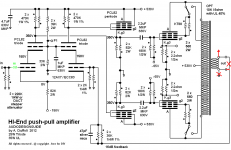
While I am writing this post, I have just realize a very important fact. This is the website from where the design comes from. Along the months that I have been gathering parts, the schematic has changed dramatically! Please check attached schematics, version 1 is the "classic" one while version 2 is the new uploaded, one month ago. I have built the second version, which connect both KT88 cathodes to ground through a current sense reistor.
Should I try to connect it like in the previous schematic version?
Anyway I have made a call to Andrea who is the designer of that circuit to see if he can throw up some light on that.
Thank you!
PP2012 - KT88 Hi-End Push Pull Amplifier
I started to getting parts and building this amplifier some months ago, and yesterday I got one of the two channels assembled. After assembling a circuit, my usual procedure is to check everything against the schematic, and if everything's OK, then double check it by drawing the schematic from the actual assemble circuit. If comparing both the original schematic and mine results in no differences, then I go ahead and light things up. May seems to be a bit paranoid, but I haven been always taught to work on the safe side.
After cabling all heaters (important! only heaters, not any other voltages from PSU), pushed valves in sockets and all lighted, check for their voltages. Good. Then I took them out and connected the rest of the voltages, adjusted trimmers to bias KT88 at -65v, and ready to go! I put the valves in again, turn the thing on with multimeter probes between the resistor cathodes on both KT88 (it's a push-pull) to check for bias (1 ohm cathode resistor, so MM at 200mv scale), and display started to show strange changes, wildly varying, 20mv, -140mv, 60, you know, all at random.
I turn off the thing and visually check if there were any loose cable, any kind of short... nothing. Turned it on again, and voltage varies randomly.
While I am writing this post, I have just realize a very important fact. This is the website from where the design comes from. Along the months that I have been gathering parts, the schematic has changed dramatically! Please check attached schematics, version 1 is the "classic" one while version 2 is the new uploaded, one month ago. I have built the second version, which connect both KT88 cathodes to ground through a current sense reistor.
Should I try to connect it like in the previous schematic version?
Anyway I have made a call to Andrea who is the designer of that circuit to see if he can throw up some light on that.
Thank you!
PP2012 - KT88 Hi-End Push Pull Amplifier
Attachments
Hi you all, I will try to do my bests to answer each one:
As far as output trafo impedance, what would be the drawbacks/pros of using a higher impedance one? As I have read, a bit lower on the raw power side, but maybe a less of distontion? Just talking from my own ignorance...
Best regards!
Before messing up with feedback I will try to see which schematic is the correct one regarding KT88's cathodes. May it seem like a bug to have them grounded?disconnect negative feedback at thr out put transformer.
if the problem magically disappers, reverse the secondary wire connections.
if not, then its associated by the power supply.
that is if the schematics are a proven design
I though that too... As far as my limited experience tell me, they are almost near to mandatory. What should do it, 1K ohm 1/2W? Anyway, I placed 1K serial resistor as grid stopper on the first valve (12AX7) that is not shown on the schematic, just because I used to with SS.Where are ther grid stoppers on the output valves? It may take off at weird frequencies!
Yes, I have an 8 ohm power resistor across the secondary of the ouput trafo. And I have shorted the input signal (RCA) to ground in order to avoid picking up aerials, RFI, etc.Do you have a load connected to the amp? Don't turn it on without! A simple 8 ohm resistor will do.
As a side comment: a 10k output transformer is a bit high impedance for KT88 @ 500V. I would expect something around 5k.
As far as output trafo impedance, what would be the drawbacks/pros of using a higher impedance one? As I have read, a bit lower on the raw power side, but maybe a less of distontion? Just talking from my own ignorance...
Best regards!
So the correct one is actually the one of the website? with both cathodes grounded, right? I have used 1 ohm resistor instead of two 2.2ohm, is that fine, right?Sorry for the mistake, the KT88 ground was missing in the first schematic.
The 2.2ohm resistors are necessary to set the correct bias with a voltmeter.
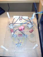
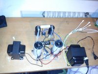
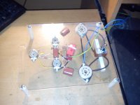
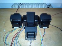
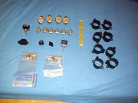
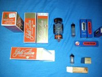
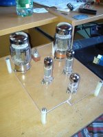
I have attached some pics I had lying around from the prototype, components, just for the fun of it... sorry for the low Q, they were taken with my phone.
Attachments
-
 904248_10151517742052649_1595341235_o.jpg147.6 KB · Views: 83
 -
 892960_10151517733857649_1396469640_o.jpg126.6 KB · Views: 83
 -
 883779_10151517742302649_127432220_o.jpg102.8 KB · Views: 76
 -
 736144_10151321845912649_1443226176_o.jpg130.2 KB · Views: 65
 -
 470688_10151306316002649_690009433_o.jpg132.2 KB · Views: 259
 -
 332425_10151306314637649_1993198528_o.jpg340.9 KB · Views: 278
 -
 322122_10151364346602649_1241504327_o.jpg184 KB · Views: 313
Before messing up with feedback....
DavesNotHere gave you a good advice. Feedback should be disconnected at this stage and should really be the last thing to look at. The amplifier must work without feedback otherwise there something fundamentally wrong with its design...
Yeah I know, I have built already one tube amp before this one. Amazing to measure 200º on the cristal bulb with my IR thermomether. But this is going to be a prototype, for testing purposes it is more than enough. The commercial name it's Perspex, I had that spare sheet around. Don't now if it's the same as plexyglassAre you using plexyglass for the base of tubes ?
The vacuum tubes are very hot !!!
Poly(methyl methacrylate) - Wikipedia, the free encyclopedia
So, next steps to take are:
-Put 10Kohm grid stoppers (carbon preferably) right onto KT88 base pins.
-Disconnect feedback
-Is 1Kohm on the 12AX7 already fine/enough?
Just to avoid any further confusion, I would like to state that the circuit I assembled is the most actual one, that is, the one with the cathodes grounded. So it points out to be a problem of oscillation or feedback network involved. Will report as soon as I am able to test it.regiregi22,
is there other problems ?
Thank you all guys for your help!
Just to avoid any further confusion, I would like to state that the circuit I assembled is the most actual one, that is, the one with the cathodes grounded. So it points out to be a problem of oscillation or feedback network involved. Will report as soon as I am able to test it.
Thank you all guys for your help!
This really, really sounds like the output transformer leads need to be reversed. As someone else pointed out, swap the output secondaries and see what happens.
I had the exact same issue with my homebuilt amp. It is very easy to do and I will bet your problem goes away.
-Put 10Kohm grid stoppers (carbon preferably) right onto KT88 base pins.
why ?
To prevent output stage oscillation. 10k might be higher than needed, but for reliability, there ought to be grid stoppers, which is most important when the tubes have a high gm.
I don't suggest carbon resistors but a metal type in parallel
Why parallel?
You mean like that (attached pic, shown on red traces)? As easy as it sound, just swaping output trafo wires?This really, really sounds like the output transformer leads need to be reversed. As someone else pointed out, swap the output secondaries and see what happens.
I had the exact same issue with my homebuilt amp. It is very easy to do and I will bet your problem goes away.
Drawn in green on the attached pic.-Is 1Kohm on the 12AX7 already fine/enough?
where 1k ?
We've been there some months agoWhy parallel?
http://www.diyaudio.com/forums/tubes-valves/226428-pairs-resistors-opposite-directions.html
I tend to agree with DF96 and the general consensus that carbon resistors tend to drift over time, they ain't moisture proof and have poor tolerance on their values. OK, those are objective facts, not something to agree, my statement was related to wether or not is makes any difference for the better. Not talking about "flavour of sound", but a measurable and/or relevant influence.
Seems to me that the tube community is the only one among all electronic related areas that strictly technically disregard modern film resistors in favour of carbon ones.
Attachments
- Status
- This old topic is closed. If you want to reopen this topic, contact a moderator using the "Report Post" button.
- Home
- Amplifiers
- Tubes / Valves
- Problem with push-pull KT88