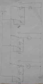
Here is my rough concept for the logic of a source selector. I wanted no microcontroller, and the concept should be easily expandable to a number of inputs.
Desired functionality:
When you push a button, any other active source is deselected, and the new source is connected, even when you release the button.
Buttons are DPDT momentary toggles or pushbuttons.
Relay coils need to be 12 VDC. 5 VDC relay coils have guaranteed turn-off voltages close to the 0.7 V diode drop.
The relay that selects the input might be the same one as for the logic, or it could be separate...
Does this idea make sense?
Attachments
I don't get it tbh ") ... you need to draw it much much clearer and with one relay in the conducting state. It seems a very "clumsy" way of doing things tbh, sorry that's not meant as a criticism.
... you need to draw it much much clearer and with one relay in the conducting state. It seems a very "clumsy" way of doing things tbh, sorry that's not meant as a criticism.
This is a simple selector (I'm sure it came from someone on the forum, maybe Lineup from a few years back) and uses one CMOS chip. No micros, no clocks.
... you need to draw it much much clearer and with one relay in the conducting state. It seems a very "clumsy" way of doing things tbh, sorry that's not meant as a criticism.This is a simple selector (I'm sure it came from someone on the forum, maybe Lineup from a few years back) and uses one CMOS chip. No micros, no clocks.
Attachments

I have built this circuit and... what could be wrong?
There's four circuits in this thread. Which one?
Hi,
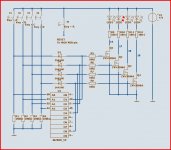
here´s another one, but with the add-on of a temporarily muting output relay.
Similar to the circuit Mooly presented it utilizes a CD4028B and the diodes D1-D4 for a hold-function.
You can connect a 100nF cap across one of the tactile input switches (Cin) to make that input a preset input.
The outputs may be switched by discrete transistors (BC550 etc.), or a transistor-array like the ULN2804 (the ULN2804 is a left-over from a earlier, bigger project, see here )
It´s a break-before-make logic with low sensitivity to switch-over noises, but to be sure one could add a temporare mute function as follows.
Diodes D5-D9 combine the unused outputs of the CD4028B and trigger one half of a CD4098B.
For a time span of the RC-time-constant (Rx1/Cx1, 1M/100nF=100ms) the output is muted.
Adding a simple R-C-D circuit plus transistor (Tr connected in series to the output-Relay transistor) one can also add delayed-turn-On/fast turn-Off functionality.
jauu
Calvin
Attachments
Last edited:
Sorry, the circuit right above my first post.
Oh, mine. Sorry it's such a crummy drawing. If it doesn't latch I would suspect either PS decoupling (lack thereof), or the cap on the clock pin. There needs to be a very brief "settling time" between setting the input pin and the rising edge on the clock pin. I used a RC circuit to set a little delay on the clock. Make sure you have a small cap on the power pin to ground, and experiment with cap values on the clock pin.
I used a 12V chip because I had a 12V circuit and it seemed easier to use the 12V supply directly than to power the chip off a 5V supply, but a small 7815 would get you that with little effort.
CMOS is very good at 'remembering' due to stray/residual charge. Circuits such as these lend themselves to being powered from a supply with a backup cap or battery. That way they deliberately remember the last state they were in. Use small FET's in place of the transistors and no current should be drawn from the backup supply.
Here's the way I did it, could be made simpler using a PIC to do all decoding and latching but I wanted a design for folks with no programming knowledge to be able to build. It uses double the amount of relays because it isolates the unwanted Grounds as well as the line signals. There is a version that can feed either of two amplifiers for when you have a separate headphone amplifier. A link to YouTube in the info presents a crazy video I quickly made to show the workings of the box.
An array of momentary push button switches could replace the infra-red controller if needed.
http://www.g4cnh.com/public/Quasar_remote_control_LATEST_6 _CHANNEL.pdf
http://www.g4cnh.com/public/Quasar_remote_control_LATEST_6 _CHANNEL_2 OUTPUT.pdf
An array of momentary push button switches could replace the infra-red controller if needed.
http://www.g4cnh.com/public/Quasar_remote_control_LATEST_6 _CHANNEL.pdf
http://www.g4cnh.com/public/Quasar_remote_control_LATEST_6 _CHANNEL_2 OUTPUT.pdf
I don't get it tbh
This is a simple selector (I'm sure it came from someone on the forum, maybe Lineup from a few years back) and uses one CMOS chip. No micros, no clocks.
Mooly & Co.:
I'll apologize for the dumb question in advance -- where are the relays connected in this circuit?
Regards,
Scott
The circuit I posted in post #2 (which I haven't built) and which came from another member would have the relays connected between the marked 14, 17, 18 and 19 and the positive supply so that the FET pulls the appropriate relay coil to ground.
Each relay coil would also need a small diode connected in inverse parallel to damp any back emf as the coil current switches on and off.
Each relay coil would also need a small diode connected in inverse parallel to damp any back emf as the coil current switches on and off.
Attachments

The circuit I posted in post #2 (which I haven't built) and which came from another member would have the relays connected between the marked 14, 17, 18 and 19 and the positive supply so that the FET pulls the appropriate relay coil to ground.
Each relay coil would also need a small diode connected in inverse parallel to damp any back emf as the coil current switches on and off.
Mooly:
Ah, now I get it. Thank you!
Regards,
Scott
The CD4028BCN should be the DIP package according to the (old) data sheet.
Widely available I would think... lets have look... so listed as CD4028BE
http://cpc.farnell.com/texas-instru...ddkey=http:en-CPC/CPC_United_Kingdom/w/search
Widely available I would think... lets have look... so listed as CD4028BE
http://cpc.farnell.com/texas-instru...ddkey=http:en-CPC/CPC_United_Kingdom/w/search
The circuit I posted in post #2 (which I haven't built) and which came from another member would have the relays connected between the marked 14, 17, 18 and 19 and the positive supply so that the FET pulls the appropriate relay coil to ground.
Each relay coil would also need a small diode connected in inverse parallel to damp any back emf as the coil current switches on and off.
Yes the circuit in post #4 works the same way. Each of the first six lines of CONN1 connects to a relay coil, and when the corresponding transistor conducts, current flows through the coil. I made this to work with a "Mezmerize" DCB1 preamp, which has a similar connector on the board.
As for the issue with circuits being energized on startup, I saw this happen exactly once in the last six or seven years since I built it. Notice there is another RC network on the CLR pin (which should actually be written as CLR with a line over it). That pin clears all the inputs when it is low. The RC network keeps the pin low for a few milliseconds at power up, which should be long enough to clear everything unless you have a longer time constant via decoupling caps on the power pin. Once the cap on the CLR pin is charged the pin stays high. I spent some time trying to force the circuit to energize two relays at once but couldn't make it happen, though of course it is theoretically possible.
Here it is in action.

- Status
- This old topic is closed. If you want to reopen this topic, contact a moderator using the "Report Post" button.
- Home
- Source & Line
- Analog Line Level
- Resistor-Diode-Relay Logic Source Selector