What is the TUBE SOUND ?
I think the biggest contribution comes from small distortion
such as 0.5% THD.
To generate 0.5% THD, I propose to install a pre processor before
solid state main amp. I did simulation with the attached circuit
schematic using 12B4A on TINA-TI simulator. The results are as follow:
Voltage Gain = 4
THD = 0.512% @0.4Vrms output
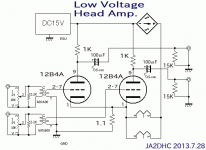
Circuit Description:
Power supply: Laptop PC's AC adapter, DC 12V out put for both
plate and heater power supply.
I eliminated the Cathode By-pass capacitor as it affects to
degrade the sonic. 300mA of 12B4A's heater current is
merged into a cathode resistor with the 12B4A's plate current.
Resulting. only 2.2 ohm of the cathode resistor is enough and
the negative feed back due to cathode resistor is minimized
I have not yet assembled the actual amp of this circuitry.
Simulation only at the moment.
'73 de JA2DHC
I think the biggest contribution comes from small distortion
such as 0.5% THD.
To generate 0.5% THD, I propose to install a pre processor before
solid state main amp. I did simulation with the attached circuit
schematic using 12B4A on TINA-TI simulator. The results are as follow:
Voltage Gain = 4
THD = 0.512% @0.4Vrms output
Circuit Description:
Power supply: Laptop PC's AC adapter, DC 12V out put for both
plate and heater power supply.
I eliminated the Cathode By-pass capacitor as it affects to
degrade the sonic. 300mA of 12B4A's heater current is
merged into a cathode resistor with the 12B4A's plate current.
Resulting. only 2.2 ohm of the cathode resistor is enough and
the negative feed back due to cathode resistor is minimized
I have not yet assembled the actual amp of this circuitry.
Simulation only at the moment.
'73 de JA2DHC
Attachments

Hi,Robert Kesh, Thanks for a quick response.
The SPICE model of 12B4A used in my simulation employees
grid current (see quoted SPICE model at the bottom). However
This SPICE model assumes only positive grid domain.
don't care negative domain of the grid (ie; don't care
the thermal velocity effect) .
'73 de JA2DHC
*
* Generic triode model: 12B4A
* Copyright 2003--2008 by Ayumi Nakabayashi, All rights reserved.
* Version 3.10, Generated on Sat Mar 8 22:41:12 2008
* Plate
* | Grid
* | | Cathode
* | | |
.SUBCKT 12B4A A G K
.PARAM X1=1 X2=0.087065329 X3=-1.2036947
.PARAM X4=0.55479636 X5=5.1134435 X6=2.7036947
.PARAM X7=0.0047680512 X8=9.2167935 X9=0.0036584566
.PARAM Y1=0.0023840256 Y2=0.0031806909
BK IK 0 V=U(V(G,K)+X1)*X7*URAMP(V(G,K)+X1+URAMP(V(A,K))/X8)^1.5+(1-U(V(G,K)+X1))*X9*(X2*URAMP(V(A,K)))^X3*(X4*URAMP(V(G,K)+X1+URAMP(V(A,K))/X5))^X6
BA A K I=URAMP((Y2*URAMP(V(A,K))^1.5)-URAMP((Y2*URAMP(V(A,K))^1.5)-V(IK)+Y1*URAMP(V(G,K))^1.5*(URAMP(V(G,K))/(URAMP(V(A,K))+URAMP(V(G,K)))*1.2+.4)))+1E-10*V(A,K)
BG G K I=Y1*URAMP(V(G,K))^1.5*(URAMP(V(G,K))/(URAMP(V(A,K))+URAMP(V(G,K)))*1.2+.4)
* CAPS
CGA G A 4.8p
CGK G K 5p
CAK A K 1.5p
.ENDS
Some people like distortion and may call it 'tube sound'. They often deny this. They may obtain the sound they prefer by misusing valves, but possibly not realising that this is what they are doing.
Others like valves for other reasons, and know that when used properly their distortion is sufficiently low that it will be inaudible and so can be ignored. Mostly, they dislike 'tube sound' as a phrase.
Others like valves for other reasons, and know that when used properly their distortion is sufficiently low that it will be inaudible and so can be ignored. Mostly, they dislike 'tube sound' as a phrase.
tube sound
I think another important aspect of "tube sound" comes from the output transformer drive. Instead of using voltage drive a speaker in solid state design, the transformer acts more like an energy drive. This in turn can achieve better dynamics when driving a nonlinear load such as speaker. So I don't think just introducing the distortion can emulate the "tube sound".
I think another important aspect of "tube sound" comes from the output transformer drive. Instead of using voltage drive a speaker in solid state design, the transformer acts more like an energy drive. This in turn can achieve better dynamics when driving a nonlinear load such as speaker. So I don't think just introducing the distortion can emulate the "tube sound".
What is the TUBE SOUND ?
tube sound originates from a time when most speakers lacked midbass BSC, simply because they didnt know better
tube amps could work like magic on that 'problem'
you might say it relates mostly to high output impedance, due to the output transformer
but its only partly true
a very simple tube preamp could also do wonders in this respect
but Im sure its much different today
speakers are much better designed
and knowledge about transistor based design have also improved some
This appears to be an attempt to turn a weakness into a virtue, by redefining reality. The correct way to deal with this is to deal with the weakness by using feedback; not try to woffle it away.yangshau said:I think another important aspect of "tube sound" comes from the output transformer drive. Instead of using voltage drive a speaker in solid state design, the transformer acts more like an energy drive. This in turn can achieve better dynamics when driving a nonlinear load such as speaker. So I don't think just introducing the distortion can emulate the "tube sound".
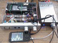
I have finished to assemble my sound processor (pre-amp)
to generate "Tube Sound"
The final schematic and external view are shown in the
attached photos.
Focus Points of circuit design
*Single LAP TOP PC use DC15V power supply to cover everything,
Plate Voltage, Heater, Power Amp (Class-D).
*Heater currents are merged into a cathode resister of 1.1 ohm
so that By-Pass capacitor can be eliminated since current feedback
is very low due to low resistance of 1.1 ohm. Channel separation is
about 50dB (measured).
*In order to avoid effect of grid current, I used input
transformer whose resistance of the secondary winding is 240ohm.
* Plate current is about 4mA (measured).
From now on, I will measure. Now I am typing this post with listening
music, good sound !
'73 de JA2DHC
Attachments
There's a fair amount of tube emulation circuits showing up in guitar amps and such. Some of them are quite good.
There seems to be two different approaches:
- DSP modeling
- Solid state circuits that create a harmonic structure similar to that of a tube.
These models/emulators seem to do a good job of modeling the effects of the tube transfer characteristic, but often not such a good job of modeling the effects of OPT saturation, etc. For hifi purposes, it wouldn't surprise me if one could design a tube emulator circuit that would get you 90 % of the "tube sound" for 10 % of the cost of a tube amp.
A tube emulator still wouldn't be as pretty as a well-excecuted tube amp, though.")
~Tom
There seems to be two different approaches:
- DSP modeling
- Solid state circuits that create a harmonic structure similar to that of a tube.
These models/emulators seem to do a good job of modeling the effects of the tube transfer characteristic, but often not such a good job of modeling the effects of OPT saturation, etc. For hifi purposes, it wouldn't surprise me if one could design a tube emulator circuit that would get you 90 % of the "tube sound" for 10 % of the cost of a tube amp.
A tube emulator still wouldn't be as pretty as a well-excecuted tube amp, though.
~Tom
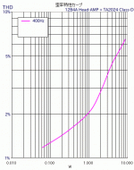
I measured the distortion characteristics as shown in the
attached photo.
I use Class-D amplifier for the final power amp. This amp uses
Tripath's TA2024 with DC15V power supply.
THD =2%@1W is the worst data among my home brew amplifiers
as is a successful result of the objective of Tube Sound Processor.
'73 de JA2DHC[/QUOTE]
attached photo.
I use Class-D amplifier for the final power amp. This amp uses
Tripath's TA2024 with DC15V power supply.
THD =2%@1W is the worst data among my home brew amplifiers
as is a successful result of the objective of Tube Sound Processor.
'73 de JA2DHC[/QUOTE]
Attachments
What is the TUBE SOUND ?
That would be a shame if some lame developer thought they could develop an app to simulate 'tube sound' for an MP3 tune to be filtered through on an iPhone or iPad. And you could select what type of tube sound. Push-Pull KT88 or 6550, SE 300B or 2A3....hmmm. Don't get them started.
Some people like distortion and may call it 'tube sound'. They often deny this. They may obtain the sound they prefer by misusing valves, but possibly not realising that this is what they are doing.
Others like valves for other reasons, and know that when used properly their distortion is sufficiently low that it will be inaudible and so can be ignored. Mostly, they dislike 'tube sound' as a phrase.
Lets have two people who need glasses.
They are looking at a fine art painting.
One of them wears thick distorted glasses. This person is the tube sound.
The other person wears thin high tech contacts.
I would rather be the person with the high tech contacts that allows me to see the picture more the way its viewed with pure eyes, then with some form of distortion thats "Warmer" that technically, and logically, distorts the image.
Why would a distorted image be a better thing then an undistorted image?
You want accuracy, extremely low distortion, high response, hi fidelity.
The relationship between Distortion and Sound is described
in the following article which is written by Pete Millett.
the Sound of Distortion
My most favorite Tube Sound comes from my 211 SET amp
with Class-A2. This amp was designed by me.
see: 211 SET
(sorry written in Japanese).
Today's sound processor aims to close to 211SET with sound.
in the following article which is written by Pete Millett.
the Sound of Distortion
My most favorite Tube Sound comes from my 211 SET amp
with Class-A2. This amp was designed by me.
see: 211 SET
(sorry written in Japanese).
Today's sound processor aims to close to 211SET with sound.
Yes. Not me, though. Read what I said.Rainwulf said:One of them wears thick distorted glasses. This person is the tube sound.
Unnecessary, given the distortion from transducers. Low, yes; extremely low, mere specmanship. Pursuing one parameter to the nth degree will usually, in real engineering, mean too much compromise on other parameters.extremely low distortion
Sorry i generalised the parameters that a hi-fi person wants.
There is a whole whack of numbers in the parameters of an audio amp. You either want zero, 1, or infinity for each one of those parameters.
I understand that transducers cause distortion. You cant escape that, but thats no reason to accept distortion in an amplifier, then call it "tube sound".
There is a whole whack of numbers in the parameters of an audio amp. You either want zero, 1, or infinity for each one of those parameters.
I understand that transducers cause distortion. You cant escape that, but thats no reason to accept distortion in an amplifier, then call it "tube sound".
Gain? Typically around 20.Rainwulf said:There is a whole whack of numbers in the parameters of an audio amp. You either want zero, 1, or infinity for each one of those parameters.
Bandwidth? Must be restricted at both LF and HF ends to avoid problems - only a fool wants a 'DC to daylight' amplifier, unless he is running off batteries in the middle of a desert.
Output impedance? Zero could increase RF pickup on cables by making them a better resonator.
No, your approach (if you really believe what you said) is naive and oversimplistic.
- Status
- This old topic is closed. If you want to reopen this topic, contact a moderator using the "Report Post" button.
- Home
- Amplifiers
- Tubes / Valves
- Tube Sound Processor