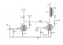
This is my new SE with GU50. Idea is "stolen" from Wavebourn. I tried 6J9P and 6J49P as input tube and I found that 6J49P sound better. I got around 12W.
schematic:
amp:
schematic:
An externally hosted image should be here but it was not working when we last tested it.
amp:
An externally hosted image should be here but it was not working when we last tested it.
Cathode resistor of GU50 not bypassed ?
No, with bypassed I have to much gain and no difference in sound. I must find the right NFB resistor, but right now I am out of 110K-1M resistors.
Doesn't 0µ1 on 100k cutoff the bass to high?
Mona
-3db is: Solve[10^5 == (1/(2*Pi*f*100*10^-9)), f] - Wolfram|Alpha
No, with bypassed I have to much gain and no difference in sound. I must find the right NFB resistor, but right now I am out of 110K-1M resistors.
"No difference".....interesting. Pentode without cathode decoupling yields gigantic output resistance. What speakers do you use ? Open baffle ? With my bassreflex speakers this would be impossible.
Nice looking build, and I like the use of the regulated screen supplies. I am inclined to jump on the bandwagon suggesting a lower feedback resistor value instead of an unbypassed cathode resistor. By quick and dirty estimate, you are getting a plate impedance of around 4kOhm with the bypass and 10kOhm without it given the current feedback scheme.
"No difference".....interesting. Pentode without cathode decoupling yields gigantic output resistance.
It doesn't mean anything. A constant current ampifier can work as good as constant voltage (a typical solid state amp) or (quasi) constant power amp (a typical zero feedback DHT).
It's not about bass reflex or dipole. It's more about drivers. A constant current amp + drivers with a good self damping (in the good sense) just work fine.What speakers do you use ? Open baffle ? With my bassreflex speakers this would be impossible.
Have you ever heard of Ultrasound?
Sito Ultrasound Main Frame
Have a look at their bass reflex loudspeakers and amplifiers. Although I disagree with the multipole concept, their standard bass reflex speakers with their high Zout amps sound very nice.
Last edited:
It doesn't mean anything. A constant current ampifier can work as good as constant voltage (a typical solid state amp) or (quasi) constant power amp (a typical zero feedback DHT)....
It means that the frequencies where the impedance of the speaker(s) is high are
strongly emphasized. For example at the bass resonance.
And those frequencies where the impedance is low are attenuated a lot.
So the frequency response of the amplifier is fully determined by the speakers.
I have understood that current drive of the speakers can work very well, but does it require quite constant speaker impedance ?
No, that's not true. If the drivers have the right parameters you don't have any emphasization. Regarding the impedance in general you can have woofer where its coil inductance will work as 1st order filter! You don't need crossover. You need a filter (just a cap if you can) for the tweeter. Some time ago there was a kit presented in an Italian DIY magazine which was exacty like that.
Yes it is true in the conditions I said. This can be calculated very easily.
But if the impedance of the speakers is relatively constant, then the emphasis / attenuation does not take place.
At low frequency the impedance can never be relatively constant and what you say simply doesn't happen. Anyway FS is one thing were people get lost when judging the performance of a system.....
Last edited:
Hey guys open new Thread!
My new schematic:
Maybe I open a new thread but you are not welcome.
Your schematic is so interesting.....!!!

My new schematic:
I simulated your circuit a little. I had to use 6j9p as a voltage amplifier because I do not have 6j49p spice model, but those two are similar tubes, basically.
I got as follows:
- Open loop gain (no 110k feedback resistor) = 34,2 dB
- Closed loop gain = 25,2 dB-----> NFB = 9 dB
- Pmax = 13 W @ THD = 9,6 %
- THD = 3,1 % @ 2 W
- Zout = 4,7 ohms.
- Quiescent current of GU-50 = 70 mA, Ig2 = 5 mA.
Are these close to your results ?
At low frequency the impedance can never be relatively constant and what you say simply doesn't happen. .....
The power delivered from a current generator increases when the load impedance increases.
Similarly, the power delivered from an amplifier having high output impedance increases when the load impedance increases.
This will especially happen when pentode output stages with no NFB are used.
I do not want to make any drawings to illustrate this but I give an example:
We have two amplifiers.
Amplifier #1 has 2.0 ohms output impedance and #2 has 28 ohms.
First we adjust both amplifiers to output 2.0 W into a 8 ohms load (which is 4 Vrms across the load).
Then we connect both amps to a load of 32 ohms representing a bass resonance of a loudspeaker.
Now amplifier #1 gives 0,69 W (= 4,7 Vrms across the load) while amplifier #2
gives 2.88 W (= 9.6 Vrms across the load).
The difference is 6.2 dB.
This is the emphasis that the higher output impedance generates at the bass resonance frequency.
The power delivered from a current generator increases when the load impedance increases.
But it's an impedance. How much of that electric power is converted into acoustic power? What is used for the rest of it? Just heat? Maybe your conventional speakers driven by your conventional amplifiers are not good enough for that! It's not about playing around with unspecified simulations about imaginary speakers.
Artosalo I have listened to one those systems. I know what I am talking about. I don't need drawings and speculations. No offense. You can say what you want but the bass from that system I listened to was simply one of the best. No emphasis at all. There are also in-room (a normal one, without special precautions) frequency responses shown and they don't look anything different from usual.
Last edited:
- Status
- This old topic is closed. If you want to reopen this topic, contact a moderator using the "Report Post" button.
- Home
- Amplifiers
- Tubes / Valves
- My new GU50 SE (all pentode)