It occurred to me that as I got noise in my own system from more capacitance than the typically .01-.1mfd people use that there is something afoot.
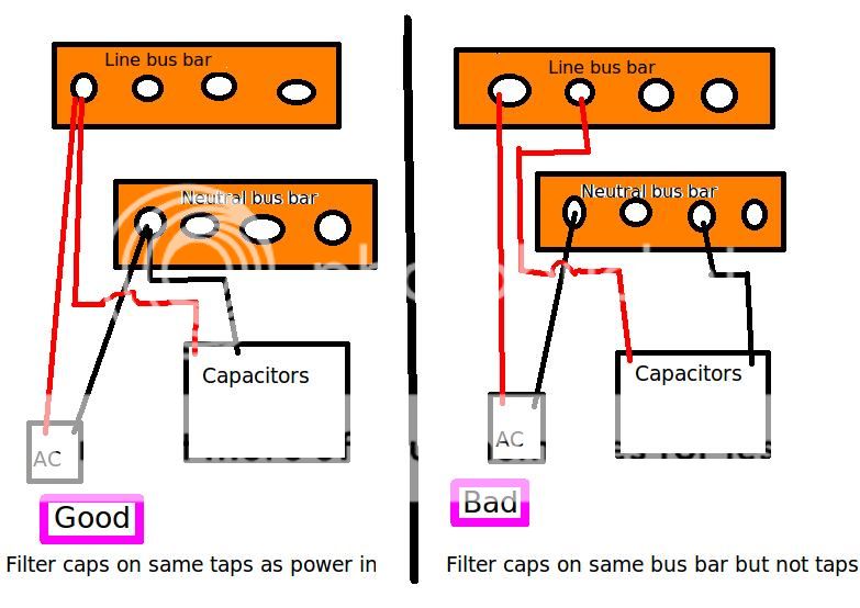
I had capacitors (X filter caps) wired in parallel to the AC receptacles on bus bars of my power distribution box. Switching from being connected just in parallel to putting the capacitors on the taps where the AC in (from wall) connects to the bus bar eliminated noise that I experienced and reduced outside noise from devices switching on and off (motor driven devices that I have to live with).
Now that I look back on it I understand what was happening. Because the capacitors put the noise 90 out of phase forward, when it dumps it back into the circuit it makes available an extra amount of electrons that other equipment can and will take advantage of because the draw is there and the cycle from where you get your power (power station) from is providing less... Essentially you can increase noise by attenuating it with capacitors on one piece of equipment and dumping it back into a bus bar, especially at a moment when the draw of equipment is higher.
You can have a filter capacitor on all of your equipment which might work or might end up amplifying noise to one device, or you can only put them on the taps of the AC in to your power distribution device before the AC receptacles.
P.S. my theory of why the noise is going back into the system could be faulty but I promise is does act that way. This idea just occurred to me that many builds of many items on here have the common practice but they are actually making more noise in their system.
Your theory is wrong. You should not need to parallel lots of capacitors. Instead, use series chokes too i.e. make a proper power filter. Failing that, buy a ready-made proper power filter.
Your equipment is not drawing power from the filter capacitors, as they are far too small in value for that unless you paralleled many thousands of them.
Your equipment is not drawing power from the filter capacitors, as they are far too small in value for that unless you paralleled many thousands of them.
Then back to the drawing board for why the behavior is thus.
They do introduce noise when not hooked up how I described. That is true. Why is a good question.
Commercial power conditioners are garbage at any price range if you ask me. Too many suck the life out of music or do very little.
By the way I do use CMC's. They help but I would not choose them over the proper amount of capacitors configured correctly, never. I am not convinced of isolation transformers at all for music. The few units I have heard sound a little flat.
Capacitors are passive devices.
There is no way they can create or amplify interferences.
What they can do is provide low impedance paths for said interferences.
This could create relatively low-impedance loops, perhaps resonances, and the resulting currents could affect some equipments in the vicinity.
This normally would not happen in a "clean" environment, but if the return wire doesnt follow the same path as the feeding wire, or if neutral and ground are intermixed in a fancy way, or anything similar, parasitic voltages could be induced in the shielding and grounding conductors.
Remedies are are good wiring practices, common mode and differential inductors, and common mode ferrites on critical paths (with more than one turn wherever possible).
Capacitors are passive devices.
There is no way they can create or amplify interferences.
What they can do is provide low impedance paths for said interferences.
This could create relatively low-impedance loops, perhaps resonances, and the resulting currents could affect some equipments in the vicinity.
This normally would not happen in a "clean" environment, but if the return wire doesnt follow the same path as the feeding wire, or if neutral and ground are intermixed in a fancy way, or anything similar, parasitic voltages could be induced in the shielding and grounding conductors.
Remedies are are good wiring practices, common mode and differential inductors, and common mode ferrites on critical paths (with more than one turn wherever possible).
That must be it. I will have pictures soon. Whatever the case we can all do ourselves a favor by not putting X capacitors in the equipment or inappropriately for how we distribute power.
Your theory is wrong. You should not need to parallel lots of capacitors. Instead, use series chokes too i.e. make a proper power filter. Failing that, buy a ready-made proper power filter.
.
Trying to filter with just a capacitor doesnt work very well.
You need an RC or an LC.
The LC solution works best but is more expensive.
A mains filter should have a 2u2 across LN and then 2 inductors in series in the L and N legs, with to a 2u2 across the output of the filter.
I used this combination with great success in some industrial equipment.
It sailed through EMC tests.
A capacitor sure, but I use a lot more than one. For good attenuation you need a fair amount. I want to link you to an old article by Magnapan but it is gone.
I am not sure what 2u2 means but I found this,
"Disadvantages of LC filters:
~ Must be designed for specified source and load reistances.
~
~ Inductors that are close to ideal inductors are difficult to design, so the final design must be "tweaked" to allow for finite Q, distributed capacitance."
There is no specific calculation in what I make. Picture soon.
We bought in a stack of mains filters from various different companies to start with but they were very expensive.
I was given the task of coming up with an in-house filter that would do teh same job but for a lot less money.
I stripped down the bought in filters and they were basically all the same with 2u2 X2 capacitors across the mains and Y rated capacitors from l+n to earth. They also had 1mH indcutors in series with the L and N.
I tweaked the filters to give best results on our EMC testing kit.
In the end I came up with a £7 filter to replace the £50 ones we were buying in.
2.2 microfaradsI am not sure what 2u2 means...
This is only true for LC filters which must provide a specific filter passband/stopband/phase response e.g as used in RF or video systems. This is the type of filter which filter books generally talk about, not a mains filter.Disadvantages of LC filters:
~ Must be designed for specified source and load reistances.
~
~ Inductors that are close to ideal inductors are difficult to design, so the final design must be "tweaked" to allow for finite Q, distributed capacitance.
If you just want to get rid of interference (the function of a mains filter) then almost any reasonable values will help. Just avoid resonance at critical frequencies. If necessary (it rarely is) cascade two filters covering different bands (e.g. HF, VHF).
Yes we do a similar thing.
I will tell you that the Magnapan article recommended a 200mfd capacitor across the N to E. I use that and a few other sizes bypassing it. The voltage is not particular on this nor do I bother with X/Y capacitors. I use cheap Solen's and Vishay filter cap.
Each AC receptacle socket I have I broke the tabs off so they are two independent sockets that both have CMCs (I use to not have that many CMCs and did one per socket but heck why not do more? it provides somewhat better filtration and more current per socket). I prefer to use the highes mh I can but depending on a few things like how much current I want a particular socket to provide it controls the size and mh. I have heard of larger inductors I could use like in Grey's power conditioners that are 10mh and handle large current. They are also enormous and potentially not as big of a benefit as they space and cost merit. Sometimes I prefer no inductor on some amplifiers so I leave some sockets without.
What do you mean by L+N to earth?
What do you mean by L+N to earth?
A Y type 2u2 capacitor from live to earth and neutral to earth.
"I use cheap Solen's and Vishay filter cap."
This is illegal in the UK, they must be X and Y rated capacitors which are self healing.
Legality? Sorry that occurs for you. The neutral to earth simply does not have the need for high voltage. I would not use them in other places, only X/Y.
They are not self healing capacitors, they are just guaranteed to fail in a specific way.
I have hear some criticism of Y capacitors and what they do to sound. I have yet to bother with them.
They are not self healing capacitors, they are just guaranteed to fail in a specific way.
I have hear some criticism of Y capacitors and what they do to sound. I have yet to bother with them.
The same is true for neutral to earth ground filter capacitors which is even more important actually, that they be arranged thusly.
The point being that if you do not wire like this you run the potential of introducing noise back into your system. The only way to protect it is to have a capacitor on every single piece of equipment, of the same value. It works for audience adept but their filtration is weak compared to what you can make for yourself. I grant that people here share that aspect with essentially everything though.
You will get more attenuation from stacking the capacitors you already have at the input taps anyways. There is a limit though where you can start attenuating the 60hz but that limit is above 100mfd where it starts to matter. For the neutral to earth it means nothing, like I said that old magnapan website article recommended 200mfd with a say 10mdf and 1mdf bypassing it. First hand experience is that it does wonders for cleaning up digital. In fact it is so powerful you can make a filter with just those in it and plug it in, in another room and still get the benefit if you are on the same breaker. (Magnapan suggested that due to hum but mine have never made a noise)
you should not be allowed to post these untruths.Legality? Sorry that occurs for you. The neutral to earth simply does not have the need for high voltage. I would not use them in other places, only X/Y.
They are not self healing capacitors, they are just guaranteed to fail in a specific way.
Legality and Safety rise above all else. This applies in this Forum as well.
A Y type 2u2 capacitor from live to earth and neutral to earth.
"I use cheap Solen's and Vishay filter cap."
This is illegal in the UK, they must be X and Y rated capacitors which are self healing.
2u2 on earth is against regulations. 4n7 is the max total capacitance allowed.
Y rated are allowed across earth and live/neutral and also across live and neutral. X rated are only allowed across live and neutral. X and Y fail in different ways.
Putting huge capacitors across the mains supply should be unnecessary, unless your supply is astonishingly dirty. Even then an LC filter will be better. They should always be mains-rated capacitors, and not create too much 'reactive power'.
If there are huge noise spikes etc. then wiring your mains bus should follow similar rules as those used for safe low noise grounding i.e. watch where the currents flow. I think I am beginning to see what you mean by capacitors "creating noise". They don't, but wiring big capacitors in the wrong place can ensure that noise already present is not suppressed but injected into equipment. You want to suppress noise at the point it enters the bus, not create noise currents through the bus itself. Hence the capacitor should be where the noise enters. With a fairly clean supply this will be less critical.
If there are huge noise spikes etc. then wiring your mains bus should follow similar rules as those used for safe low noise grounding i.e. watch where the currents flow. I think I am beginning to see what you mean by capacitors "creating noise". They don't, but wiring big capacitors in the wrong place can ensure that noise already present is not suppressed but injected into equipment. You want to suppress noise at the point it enters the bus, not create noise currents through the bus itself. Hence the capacitor should be where the noise enters. With a fairly clean supply this will be less critical.
you should not be allowed to post these untruths.
Legality and Safety rise above all else. This applies in this Forum as well.
What untruth do you speak about? The capacitors ARE guaranteed to fail in a specific way and that is why they are used in circuit environments that have more potential danger.
Using not low but lower voltage capacitors on neutral to earth makes perfect sense because you are only removing inducted charge. Without line connected in anyway there is not a complete circuit so no matter which direction the AC flows it will never have current from the fusebox, transformer outside, power substation, or power producer. It is not possible and that is why line is called line and neutral is not called line 2. Plus I trust Magnapan's techs more than you.
DF96 you can say what you will but until you have heard you just do not know. It is easy to argue about what we think is going on based on all the theories we are aware of but... Hands down I tell you that my way of power conditioning improves what people thought were dedicated circuits to their system in a neighborhood that seems fairly clean with adequate power. Even non-audiophiles can tell right away. You just have to hear to understand. My former roommate requested I get my unit back when I let a friend borrow it to try in his system. My roommate just listened to music and was not in the slightest way an audiophile but he KNEW when it was gone.
I use CMC's. They have extremely low resistance so as far as inductors go they may not be creating the particular crossover you have in mind but they do very well at removing noise. Coilcraft Combination Line Filter Choke Those are some that I like to use but for larger power requirements sometimes I get some off of digikey but for anything that uses large current flow I typically prefer nothing. I am playing with the idea of very large ones like in Grey units but I am not sure there is a way to use them due to size.
However the LC does sound interesting but it sounds like something that would have to be used inside of a component due to the fact of what I posted earlier about in order for it to work, from what I know, it is specific to the load. To me that would mean that changing loads (plugging in new or removing equipment) would mean changing the LC to correct. Let me know if I am wrong and I would love an example of an LC circuit you might use.
I appreciate the good explanation of noise. It still brings up the point that X capacitors over AC in on equipment pieces does have the potential for introducing noise in non-perfect environments, which is pretty much any environment.
- Status
- This old topic is closed. If you want to reopen this topic, contact a moderator using the "Report Post" button.
- Home
- Design & Build
- Construction Tips
- X1/X2 Capacitors AC in, adding noise to the system!?